EasyManua.ls Logo

Twin Tec 1005 User Manual

Twin Tec 1005
10 pages
To Next Page IconTo Next Page
Page #1 background imageLoading...
Page #1 background image
Daytona Twin Tec LLC, 933 Beville Road, Suite 101-H, S. Daytona, FL 32119 Model 1005
(386) 304-0700 www.daytona-twintec.com
5/2015
Page 1
Twin Tec
Installation Instructions
for Ignition Model 1005
CAUTION: CAREFULLY READ INSTRUCTIONS BEFORE PROCEEDING. NOT LEGAL FOR SALE
OR USE IN CALIFORNIA OR ON ANY POLLUTION CONTROLLED VEHICLES.
OVERVIEW
Twin Tec ignition Model 1005 is intended for use
with Harley-Davidson
Evolution
type motorcycle
engines. The Model 1005 replaces the original
equipment (OE) electronic ignition system on 1978-99
models. The unit mounts in the gear case cover and
uses the standard H-D
timing rotor. It can also be
used on earlier models with breaker points and
mechanical advance. Please note that the 1005S-EX is
recommended for 1998 and later Sportster
models as
it mates directly with the OE wiring harness.
The Model 1005 offers adjustable advance,
adjustable RPM limit settings in 100 RPM increments,
and switch selectable single or dual fire modes. Single
fire mode improves starting, reduces the occurrence of
backfiring at low RPM, and improves power at high
RPM. A red status LED flashes when the engine
reaches top dead center (TDC) and allows easy static
timing. The status LED also provides diagnostic
information. A green VOES LED illuminates when the
VOES (vacuum switch) input is active.
A special feature allows use of the tachometer
wire for a PC link to a laptop computer when the
engine is not running. Individual units can be
programmed with a custom advance curve and other
engine parameters such as rear cylinder timing offset.
The use of the tachometer wire for the PC link
eliminates the need to remove the outer cover plate.
All Model 1005 units log engine operating data
that may be downloaded and viewed with our
Operating Statistics software. Model 1005 units
manufactured starting January, 2006 include a build-in
temperature sensor and logging of temperature data.
AVOIDING HEAT RELATED
FAILURES
Heat kills electronics. The Model 1005 uses
electronic devices rated for operation at 105 deg C
(221 deg F), the highest rating available. The unit can
tolerate somewhat higher temperatures, but exposure
to temperatures above 125 deg C (257 deg F) will
greatly reduce life expectancy. We sometimes see
problematic applications where several module failures
have occurred. The failure mode is a classic thermal
intermittent where the module stops firing one cylinder
when it gets hot. We have found that these problematic
applications share one or more of the following
characteristics:
VOES switch removed or non-functional. All street
driven engines require vacuum advance. Without
vacuum advance at idle and part throttle,
thermodynamic efficiency is reduced and engine
temperatures increase significantly.
Improper carburetor jetting resulting in lean air/fuel
ratio (AFR). A lean AFR will cause the engine to
run very hot. All performance engine modifications
necessitate carburetor rejetting. Carburetors are
never correctly jetted out-of-the-box. The only
practical means of correctly jetting a carburetor is
to test the motorcycle on a chassis dyno equipped
with an exhaust gas sniffer or to use our WEGO
system.
Lack of an oil cooler on a 95 CID or larger engine.
Exhaust pipe without heat shield in close proximity
to the nose cone.
If any of the above applies to your application,
the Model 1005 may be exposed to excessive
temperatures resulting in reduced life expectancy. Use
an infrared thermometer to check the module
temperature. Can you also our Operating Statistics
software to monitor temperature levels. If excessive
temperatures are encountered and cannot be
remedied, you should consider using an external
module such as our Model 1006 or 1007.
INCLUDED AND ADDITIONAL
REQUIRED PARTS
All units include a parts bag with crimp terminals
for coil and VOES hookup and a Packard Weather
Pack connector set intended for installation on the
tachometer wire to provide an access point for the PC
link.
FL series Big-Twin
models manufactured prior
to 1985, FX series Big-Twin
and XL Series Sportster
models manufactured prior to 1984, all Sportster
1200S models, and all models with original equipment
Question and Answer IconNeed help?

Do you have a question about the Twin Tec 1005 and is the answer not in the manual?

Twin Tec 1005 Specifications

General IconGeneral
BrandTwin Tec
Model1005
CategoryMotorcycle Accessories
LanguageEnglish

Summary

Product Overview and Features

Overview of Model 1005

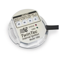
Introduction to the Twin Tec ignition Model 1005 for Harley-Davidson engines.

Key Features and Capabilities

Details adjustable advance, RPM limits, single/dual fire modes, and status LEDs.

PC Link and Data Logging

Explains using the tachometer wire for PC connection and engine data logging.

Avoiding Heat Related Failures

Causes of Overheating

Identifies factors like faulty VOES, lean jetting, and exhaust proximity.

Mitigation and Solutions

Suggests temperature monitoring and considering alternative modules.

Included and Additional Parts

Parts Included with Unit

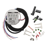
Lists terminals for coil/VOES and Packard Weather Pack connectors.

Required Timing Rotor

Specifies H-D® timing rotor P/N 32402-83 or equivalent for specific models.

Installation Procedure

Preparation and Initial Steps

Disconnecting battery, removing gear case cover, and sensor plate/points.

Mounting and Wiring the Unit

Installing the Model 1005 unit and routing the wiring harness.

Connecting to Ignition Coil

Routing harness to ignition coil and securing it away from hot areas.

Operating Modes and Settings

Mode Switch Selection

Details the 10-position rotary switch for selecting advance curves and modes.

Advance Curve Families

Explains use of street vs. race advance curves based on engine modifications.

Timing Settings and Tuning

Recommended Timing Settings

Provides starting points for street and race advance curves based on octane.

Static Timing Procedure

Step-by-step guide for setting initial timing using the red status LED.

Precise Timing Procedure

Using a timing light for advanced timing adjustments with VOES enabled.

Engine Parameters and Features

RPM Limiter Setting

Instructions for setting the RPM limit using rotary switches.

Tuning Tip: Air/Fuel Ratio

Emphasizes checking AFR and rejetting carburetors before ignition timing.

General Recommendations and Considerations

Coil Primary Resistance

Recommends coil primary resistance not less than 3 ohms, warning against Twin Cam 88 coils.

Spark Plug Wires

Suggests spiral core spark plug cables for durability over OE carbon core.

Tachometer Compatibility

Confirms compatibility with ground sensing tachometers and red LED function.

VOES Input Functionality

VOES for Vacuum Advance

Explains VOES role in providing vacuum advance for idle stability and fuel economy.

VOES Grounding and LED

Details how VOES grounds purple/white wire for advance and green LED indication.

VOES Recommendations

Recommends specific VOES units for stock or high-performance engines.

PC Link Cable and Software

USB Interface Cable

Details the P/N 18014 USB interface for PC connectivity.

PC Link Software

Introduces PC Link Evo and Operating Statistics software for configuration and data.

Special Application Modes

Kick Start Applications

Explains programming for kick start mode on units manufactured after January 2006.

VOES Input for Retard

Describes using the VOES wire as a retard input for turbocharger/nitrous applications.

Troubleshooting

Troubleshooting Flowchart

A flowchart to diagnose and resolve common issues with the ignition module.

Troubleshooting Tip: Static Timing

Highlights improper static timing as a common cause for non-starting engines.

Related product manuals