Do you have a question about the twintex TP-1305 and is the answer not in the manual?
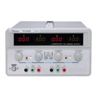
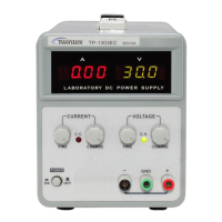
Diagrams illustrating the front panel layout of various TP series models.
Detailed explanation of the function of each front panel control and indicator.
Identification and explanation of components located on the rear panel.
Essential safety and installation guidelines for operating the power supply.
Step-by-step procedure for accurately setting the current limit.
Instructions for configuring and setting the desired constant voltage output.
Explanation of Constant Current (CC) and Constant Voltage (CV) operating modes.
Instructions and warnings for replacing blown fuses safely.
Procedure to change the unit's input AC voltage setting.
Guidelines for safely cleaning the instrument without causing damage.
The Twintex TP Series Single Channel DC Power Supply is a regulated power supply designed for use in laboratories, universities, and production lines. It offers continuously adjustable output voltage and current, making it a versatile tool for various circuit design and testing applications.
The primary function of the TP Series power supply is to provide a stable and adjustable DC voltage and current source. It can operate in either constant voltage (CV) or constant current (CC) mode, automatically switching between them depending on the load conditions and preset limits. This dual-mode operation ensures flexibility and protection for the connected device. The output voltage can be adjusted from 0 up to the unit's rating, and the load current can range from 0 up to the rating current.
The power supply features digital LED displays for both voltage and current, allowing for accurate readings of the output. Some models also include an output ON/OFF switch, which provides a convenient way to enable or disable the power output without changing the voltage and current settings. Additionally, certain models offer a fixed DC 5V/1A output, which can be useful for powering specific components or circuits that require a standard 5V supply. Overload protection circuits are integrated to safeguard both the power supply and the connected load from excessive current conditions.
Operating the TP Series power supply involves several key steps to ensure safe and effective use. Before powering on, it's crucial to ensure that the AC input voltage is within the specified range (±10% of 110V or 220V, 50/60Hz). Proper grounding of the power cord is essential to prevent electrical shock. The unit should be installed in a location that allows for adequate ventilation, and the ambient temperature should not exceed 40°C to prevent damage.
Setting Current Limit: To set a current limit, first determine the maximum safe current for the device to be powered. Temporarily short the positive and negative output terminals with a test lead. Then, rotate the COARSE VOLTAGE control until the CC indicator lights up, signifying constant current mode. Adjust the CURRENT COARSE and FINE controls to set the desired current limit, observing the value on the ammeter. Once the limit is set, do not change the CURRENT control settings. Finally, remove the short and connect the load for constant voltage operation.
Setting Constant Voltage: To set a constant voltage, turn on the power supply. The CV indicator should light up. Use the COARSE and FINE VOLTAGE controls to adjust the output voltage to the desired level. For models equipped with an output ON/OFF button, press it to enable the voltage output to the terminals; the OUTPUT indicator will light up. For models without this function, the voltage will be supplied immediately upon power-on.
C.C and C.V Mode Operation: In constant voltage (CV) mode, if the output voltage drops below the preset value and the CC indicator lights up, it means the unit has entered over-current protection and automatically switched to constant current mode. In this situation, the user should check the load or increase the current set value. Conversely, in constant current (CC) mode, if the output current falls below the preset value and the CV indicator lights up, the unit has automatically switched to constant voltage mode. The user should then check the load or increase the preset voltage value.
General Precautions: It is recommended to operate the instrument under its rated main supply. For prolonged operation, especially under heavy loads, it is suggested to use 60-70% of the full load capacity to prevent rapid aging of the unit. Frequent short-circuit operations should be avoided. When connecting a load, it is advisable to adjust the voltage knob to its minimum value before turning on the instrument, and then gradually adjust the voltage/current to the targeted values. Special care should be taken when dealing with voltages exceeding 60V DC, as they pose a lethal shock hazard.
Regular maintenance helps ensure the longevity and reliable operation of the TP Series power supply.
Fuse Replacement: If the power supply fails to operate and neither the CV nor CC indicators light up, it may indicate a blown fuse. The fuse is located on the rear panel. Before replacing the fuse, it is crucial to disconnect the power cord. The fuse should only be replaced with one of the correct rating and type (250V of the specified type and rating) to ensure continued fire protection and to protect the transformer and internal circuits. The manual provides a table detailing the correct fuse ratings for different models and input voltages (110VAC or 220VAC).
Line Voltage Conversion: The power transformer is designed to operate with either 110V or 220V AC line voltage (±10%, 50/60Hz). The unit is factory-set to a specific line voltage, which is indicated on the rear panel. To convert the unit to operate with a different line voltage, first ensure the power cord is unplugged. Then, change the AC select switch on the rear panel to the desired line voltage position. It is important to note that a change in line voltage may also necessitate a corresponding change in the fuse value, so the correct fuse must be installed as per the instructions in the manual. If the output voltage is unstable, it is recommended to check if the AC line voltage is less than 207V (for 220V setting) or 105V (for 110V setting).
Cleaning: To clean the power supply, use a soft cloth lightly dampened with a solution of mild detergent and water. Avoid spraying cleaner directly onto the instrument, as this could lead to liquid leaking into the cabinet and causing damage. Harsh chemicals such as benzene, toluene, xylene, acetone, or similar solvents, as well as abrasive cleaners, should not be used on any part of the power supply.
Should any problems arise that cannot be resolved using the provided instructions, users are advised to contact their local distributor or the manufacturer for assistance.
| Model | TP-1305 |
|---|---|
| Category | Power Supply |
| Input Voltage | 100-240VAC |
| Output Current | 5A |
| Frequency | 50/60Hz |
| Efficiency | 85% |
| Protection | Short Circuit |
| Cooling | Natural Convection |