Do you have a question about the twintex TP-3020 and is the answer not in the manual?
Technical specifications for TP-1303/1305/1603 series, including voltage/current regulation, ripple, and display.
Technical specifications for TP-3010/6005/3020/6010 series, covering voltage/current regulation, ripple, and accuracy.
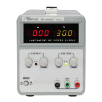
Illustrates the front panel components and layout for the TP-1303EC, TP-1305EC, and TP-1603EC models.
Illustrates the front panel components and layout for the TP-1303C, TP-1305C, and TP-1603C models.
Illustrates the front panel components and layout for the TP-1303, TP-1305, and TP-1603 models.
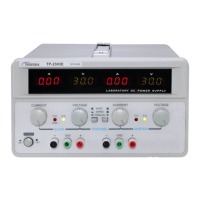
Illustrates the front panel components and layout for the TP-3010, TP-6005, TP-3020, and TP-6010 models.
Illustrates the rear panel components for 30V/3A, 30V/5A, and 60V/3A models.
Illustrates the rear panel components for the TP-3010 and TP-6005 models.
Illustrates the rear panel components for the TP-3020 and TP-6010 models.
Provides detailed descriptions of each control and indicator on the front panel of the power supply.
Describes the rear panel controls and connectors, including power socket, fuse holder, and AC input selector.
Details essential safety precautions for AC input, installation, and operating environment temperature.
Step-by-step instructions on how to determine and set the current limit for the power supply.
Instructions on how to set the constant voltage output, including the use of controls and indicators.
Explains the behavior of the power supply when operating in Constant Current (CC) and Constant Voltage (CV) modes.
Instructions for replacing blown fuses, emphasizing correct rating and safety precautions.
Details the procedure for converting the power supply between 110V and 220V line voltages.
Guidelines on how to clean the power supply safely and effectively, avoiding damage.
| Brand | twintex |
|---|---|
| Model | TP-3020 |
| Category | Power Supply |
| Language | English |