EasyManua.ls Logo

Tyco CIM800 - User Manual

Tyco CIM800
8 pages
Print Icon
To Next Page IconTo Next Page
Loading...
CIM800 Contact Input Module – Installation Instructions MZX CIM800
Installation Instructions Doc. version 4.0 1/8
CIM800 Contact Input Module – Installation
Instructions
Technical specification
Electromagnetic Compatibility
The CIM800 complies with the following:
Product family standard EN 50130-4 in
respect of Conducted Disturbances, Radiated
Immunity, Electrostatic Discharge, Fast Tran-
sients and Slow High Energy
EN 61000-6-3 for emissions
Introduction
The CIM800 Contact Input Module is designed
to monitor fire contacts such as extinguishing
system control, ventilation control, fire door con-
trol etc. The CIM800 can be configured as:
Two spur circuits (Class B) monitoring multi-
ple normally open contacts, with short circuit
giving a fault output.
Fig. 1: CIM800 Contact Input Module
Parameter Value
Type Identification
Value:
145
System Compatibility: Use only with MX
Fire Alarm Control-
lers
Environment: Indoor Application
only
Operating Temperature: -25 °C to +70 °C
Storage Temperature: -40 °C to +80 °C
Operating Humidity: Up to 95 % non-
condensing
Dimensions (HWD): 87 x 148 x 14 mm
Weight: 100 g
Mounting Require-
ments:
One MK backbox
surface mount or an
ANC-8 ancillary
housing
Table 1: Technical Specifications
Battery Requirements:
Standby current:
Alarm current:
0.505mA
4.5mA
Wire Size:
Min 1.5 mm
2
Max 2.5 mm
2
Maximum Wiring
Resistance Monitored
Circuit:
10 ohm
Addressable Device
Conditions:
Normal
Active
Short Circuit wir-
ing fault
Open Circuit
wiring fault
Device Type
Invalid
Device No
Response
Parameter Value
Table 1: Technical Specifications
Question and Answer IconNeed help?

Do you have a question about the Tyco CIM800 and is the answer not in the manual?

Summary

Technical Specification

Electromagnetic Compatibility

Introduction

Features

Wiring Notes

Mounting

Installation into ANC-8 Ancillary Housing

Details how to assemble MX800 modules into an ANC-8 ancillary housing.

Installation to M520 Double Gang Cover

How to Install MX800 Modules to M520 Double Gang Cover

Instructions for fitting CIM800 modules into an M520 double gang cover, including sealing.

Address Settings

Cabling

Associated Equipment

Ordering Information

Overview

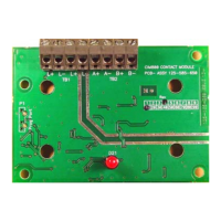
The CIM800 Contact Input Module is a device designed to monitor fire contacts, such as those found in extinguishing system controls, ventilation controls, and fire door controls. It is compatible with MX Fire Alarm Controllers and is intended for indoor applications only.

Technical Specifications:

  • Type Identification Value: 145
  • Operating Temperature: -25 °C to +70 °C
  • Storage Temperature: -40 °C to +80 °C
  • Operating Humidity: Up to 95% non-condensing
  • Dimensions (HWD): 87 x 148 x 14 mm
  • Weight: 100 g
  • Battery Requirements:
    • Standby current: 0.505mA
    • Alarm current: 4.5mA
  • Wire Size: Minimum 1.5 mm², Maximum 2.5 mm²
  • Maximum Wiring Resistance Monitored Circuit: 10 ohm
  • Addressable Device Conditions: Normal, Active, Short Circuit wiring fault, Open Circuit wiring fault, Device Type Invalid, Device No Response.

Electromagnetic Compatibility:

The CIM800 complies with:

  • Product family standard EN 50130-4 for Conducted Disturbances, Radiated Immunity, Electrostatic Discharge, Fast Transients, and Slow High Energy.
  • EN 61000-6-3 for emissions.

Function Description and Usage Features:

The CIM800 can be configured in several ways to monitor various types of contacts:

  • Two spur circuits (Class B):
    • Monitoring multiple normally open contacts, with a short circuit giving a fault output.
    • Monitoring single normally closed contacts, with a short circuit giving a fault output.
    • Monitoring multiple normally open contacts, with a short circuit giving an alarm.
  • Single loop circuit (Class A):
    • Monitoring a normally open contact, with a short circuit giving a fault output.
    • Monitoring a normally closed contact, with a short circuit giving a fault output.
    • Monitoring multiple normally open contacts, with a short circuit giving an alarm.

Key Features:

  • Identifies all monitored contacts and signals to the Fire Controller, including the status of monitored contacts and wiring.
  • Can monitor a single normally closed contact.
  • Can monitor two Class B spur circuits or a single Class A loop circuit.
  • When two Class B spur circuits are connected, they must be of the same style. An active monitored contact on either spur circuit will cause the CIM800 to report the Active State to the MX controller.
  • An LED reports the CIM800 status to the user. The LED lights when the monitored contact switches to the active (off-normal) state. When normally off, the LED will pulse when the CIM800 is polled by the controller.

Mounting:

The CIM800 can be installed in an ANC-8 ancillary housing or an M520 double gang cover.

Installation into an ANC-8 Ancillary Housing:

  1. Assemble the required ancillary PCBs onto the chassis plate, fixing them as shown in Fig. 3.
  2. Assemble the chassis plate into the housing and secure it using a fixing screw (Fig. 2).
  3. Connect the chassis plate earth lead to the housing (Fig. 2).
    • Caution: Ensure only nylon stand-offs and washers are used.

Installation to M520 Double Gang Cover:

  1. Assemble the CIM800 to the M520 Double Gang cover using the four screws and washers provided.
  2. Fit the cover onto an MK backbox.
  3. If an IP22 rating is required, apply Loctite S1595 silicone sealant around the LED, ensuring it fills the small gap between the LED and its hole in the cover. Avoid smearing sealant over the LED surface; a fine nozzle is recommended.

Address Settings:

The CIM800 has a default factory set address of 255. This address must be set to the loop address of the device using the 801AP MX Service Tool. Programming can be done either prior to installation using the internal programming port (Fig. 4) or after installation using the programming port on the front cover (Fig. 6).

  • Notice: Once the address is programmed, record the device location and address number on site drawings.

Cabling:

Cables must be selected according to Publication 17A-02-D and BS5839 requirements. Two pairs of connection terminals (L+ and L-) are provided on the terminal block for connecting the module to the addressable circuit. A maximum of one 1.5mm² or one 2.5mm² cable can be connected at any one terminal.

  • Notice:
    • There are no user-circuit required settings (switches or headers) on the CIM800.
    • All wiring must conform to the current edition of IEE Wiring Regulations and BS5839 part 1.
    • All conductors must be free of earths.
    • Fit the PCB to the M520 cover/ANC-8 ancillary housing.
    • Connect wiring to the monitored contact.
    • Verify the correct polarity of wiring before connecting the CIM800 to the addressable loop.
    • If only one circuit is used, the user circuit must be terminated with 200/100 ohm resistors in parallel or a single 68 ohm EOL resistor.
    • MX CONSYS configuration selection: style C (normally closed), Mode 3.

Typical Wiring Configurations:

  • Spur Circuits (Class B) Normally Closed Contacts (Fig. 7): Short Circuit A+ to A- or B+ to B- = Fault. MX CONSYS configuration selection: style C (normally open), Mode 2. If only one circuit is used, terminate with a 200 ohm EOL resistor.
  • Spur Circuits (Class B) Normally Open Contacts (Fig. 8): Short Circuit A+ to A- or B+ to B- = Fault. MX CONSYS configuration selection: style E (normally closed), Mode 6.
  • Loop Circuit (Class A) Normally Closed Contact (Fig. 9): Short Circuit A+ to A- or B+ to B- = Fault. MX CONSYS configuration selection: style E (normally open), Mode 5.
  • Loop Circuit (Class A) Normally Open Contact (Fig. 10): Short Circuit A+ to A- or B+ to B- = Fault. MX CONSYS configuration selection: style B (normally open), Mode 1. If only one circuit is used, the other circuit must be terminated with a 200 ohm EOL resistor.
  • Spur Circuit (Class B) Normally Open Contacts (Fig. 11): Short Circuit between A+ and A- or B+ and B- = Alarm.
  • Loop Circuit (Class A) Normally Open Contacts (Fig. 12): Short Circuit between A+ and A- or B+ and B- = Alarm. MX CONSYS configuration selection: style D (normally open), Mode 4.

Associated Equipment:

The module fits onto a standard dual-gang MK box or an ANC8 ancillary housing.

Maintenance Features:

The manual does not explicitly detail maintenance features beyond the initial installation and configuration. However, the ability to program the address after installation and the visual LED indicator for status provide some diagnostic capabilities.

Tyco CIM800 Specifications

General IconGeneral
BrandTyco
ModelCIM800
CategoryI/O Systems
LanguageEnglish

Related product manuals