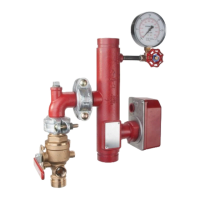
Model RM-1
Riser Manifold
Commercial and Residential
Page 1 of 8 AUGUST 2021 TFP963
Worldwide
Contacts
www.tyco-fire.com
IMPORTANT
Refer to Technical Data Sheet
TFP2300 for warnings pertaining to
regulatory and health information.
General
Description
The TYCO commercial and residential
Model RM-1 Riser Manifold provide
the necessary waterflow alarm, pres-
sure gauge, alarm test orifice, drain,
and sight glass equipment in a single
assembly for use in NFPA 13 com-
mercial sprinkler systems and in NFPA
13D/13R residential sprinkler systems
as follows:
NFPA 13*
• 1-1/2 in. (DN40)
Male Thread x Female Thread
• 2 in.– 6 in. (DN50 – DN150)
Groove x Groove
NFPA 13D
• 1 in. (DN25)
Female Thread x Female Thread
NFPA 13R
• 1-1/2 in. (DN40)
Male Thread x Female Thread
• 2 in. (DN50)
Groove x Groove
* Although the Riser Manifold described in this techni-
cal data sheet is intended for NFPA 13 sprinkler sys-
tems, it may be used for NFPA 13D or 13R residential
sprinkler systems, where a test orice of 2.8K or 4.2K
is acceptable.
The variety of sizes and grooved end
connections allow cost effective and
easy transition to check valves, control
valves, and system piping. The Model
RM-1 Riser Manifolds may be installed
either horizontally (flow switch on top)
or vertically (flow going up) orientation,
for both single sprinkler rises and floor
control in high-rises.
Optional Pressure Relief Kits feature a
175 psi pressure relief valve and trim
components for convenient integration
into commercial and residential riser
manifold assemblies.
The pressure relief valve, installed in
manifold assemblies above the nor-
mally closed test and drain or drain
valve, automatically bleeds system
pressure exceeding 175 psi through a
flexible hose connected to the mani-
fold drain outlet (Ref. Figure 5), reduc-
ing system pressure to 175 psi.
NOTICE
The Model RM-1 Riser Manifolds
described herein must be installed
and maintained in compliance with this
document, as well as with the applica-
ble standards of the NATIONAL FIRE
PROTECTION ASSOCIATION (NFPA),
in addition to the standards of any other
authorities having jurisdiction. Failure
to do so may impair the performance
of these devices.
The owner is responsible for main-
taining their fire protection system
and devices in proper operating con-
dition. Contact the installing contrac-
tor or product manufacturer with any
questions.
Technical
Data
Approvals
UL and ULC Listed
FM Approved
Listed by California State Fire Marshall
Maximum Working Pressure
300 psi (20,7 bar)
Friction Loss
See Table A
Test Orifice
1 in.– 3 in. (DN25 – DN80) Manifolds: 2.8K
4 in.– 6 in. (DN100 – DN150) Manifolds: 4.2K
Finish
Red Painted