TFP963
Page 7 of 8
Care and
Maintenance
TYCO Riser Manifolds RM-1 must be
serviced and maintained in accordance
with this section.
Before closing a fire protection system
control valve for inspection or main-
tenance work on the fire protection
system that it controls, permission to
shut down the effected fire protection
system must first be obtained from
the proper authorities and all person-
nel who may be affected by this action
must be notified.
After placing a fire protection system
in service, notify the proper authorities
and advise those responsible for moni-
toring proprietary and/or central station
alarms.
The owner is responsible for the
inspection, testing, and maintenance of
their fire protection system and devices
in compliance with this document, as
well as with the applicable standards
of the NATIONAL FIRE PROTECTION
ASSOCIATION (e.g., NFPA 25), in addi-
tion to the standards of any authority
having jurisdiction. Contact the install-
ing contractor or product manufacturer
with any questions.
It is recommended that automatic
sprinkler systems be inspected, tested,
and maintained by a qualified Inspec-
tion Service in accordance with local
requirements and/or national codes.
Note: No attempt is to be made to
repair any Riser Manifold component
in the field. Only the pressure gauge,
waterflow alarm switch, or relief valve
can be replaced. If any other problems
are encountered the entire riser mani-
fold must be replaced.
The alarm/flow test procedure will
result in operation of the associated
alarms. Consequently, notification
must be given to the owner and the fire
department, central station, or other
signal station to which the alarms are
connected, and notification must be
given to the building occupants.
The following inspection procedure
must be performed as indicated, in
addition to any specific requirements
of the NFPA, and any impairment must
be immediately corrected:
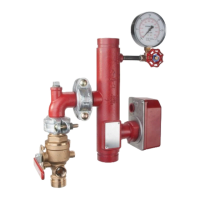
Alarm/Flow Test Procedure
Step 1. Place the Model TD-1 Test and
Drain Valve in the TEST position (Ref.
Figure 7). On residential assemblies
without a test orifice, temporarily install
a test orifice in the drain outlet and fully
open the Drain Valve. Make certain
that drainage water will not cause any
damage or injury.
Step 2. Verify operation of associated
alarms.
Step 3. Verify that the residual (i.e.,
flowing) pressure indicated by the pres-
sure gauge is no less that originally
recorded for the system when it was
first installed.
Step 4. Close the Drain Valve on the
Residential models and the Test and
Drain valve on commercial models.
Step 5. Verify that the static (i.e., not
flowing) pressure indicated by the pres-
sure gauge is no less that originally
recorded for the system when it was
first installed.
DRAIN MARKING
ON HANDLE
POSITIONED
ON DETENT
OFF MARKING
ON HANDLE
POSITIONED
ON DETENT
SET
FRONT
SIGHT
FLOW
TEST
DRAIN
CONNECTION
TEST MARKING
ON HANDLE
POSITIONED
ON DETENT
DRAIN
MODEL TD-1
TEST AND
DRAIN
VALVE
FIGURE 7
MODEL RM-1 COMMERCIAL RISER MANIFOLD
TD-1 TEST AND DRAIN VALVE OPERATION
 Loading...