TFP963
Page 4 of 8
Manifold
Installation
TYCO Model RM-1 Riser Manifold
must be installed in accordance with
this section.
The Model RM-1 Riser Manifold may be
installed either horizontally (flow switch
on top) or vertically (flow going up). The
inlet of the Riser Manifold may be con-
nected directly to a shut-off control
valve.
Notes:
Where applicable pipe thread sealant
is to be applied sparingly. Use of a
non-hardening pipe thread sealant is
recommended.
Never remove any piping component
nor correct or modify any piping defi-
ciencies without first depressurizing
and draining the system.
Provisions for an alarm test flow on
Residential Models must be made.
The alarm test flow is to be through
an orifice having a flow capacity equal
to or smaller than the smallest orifice
sprinkler in the system. One of two
options can be considered. The first
option is to temporarily install a test
orifice in the outlet of the drain line
prior to performing the alarm test. The
second option is to install an Inspec-
tor’s Test Connection downstream of
the Waterflow Alarm Switch.
Step 1. Install the manifold body with
the flow arrow pointing in the down-
stream position using threaded con-
nections and/or listed mechanical
grooved connections, as applicable.
Step 2. Connect the drain line and on
commercial manifolds set the Model
TD-1 Test and Drain Valve to the OFF
position or on residential manifolds
close the drain valve.
Step 3. Refer to Figure 6 for wiring
guidance. All wiring must be performed
in accordance with the authority having
jurisdiction and/or the National Electri-
cal Code.
Step 4. Refer to Figure 5 for Optional
Pressure Relief Trim installation.
Step 5. Place the system in service
by filling the system with water. When
filling the system, partially open the
control valve to slowly fill the system.
Filling the system slowly will help avoid
damaging the waterflow alarm switch.
After the system is fully pressurized,
completely open the control valve.
Step 6. Secure all supply valves open.
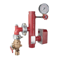
NO DESCRIPTION P/N
1 300 psi/2000 kPa
Water Pressure Gauge . . 90050001
2 Ball Valve, 1” (DN25)....97111603
3 Flow Switch, VSR-M,
2” (DN50) ............91144802
4 Field Replaceable
Retard/Switch.........91144800
3-7/8"
(100 mm)
1/2"
(13 mm)
5"
(127 mm)
4-1/8"
(105 mm)
2"
(GROOVED)
2"
(GROOVED)
13"
(330 mm)
2
3, 4
1
FLOW
11-7/8"
16"
OPTIONAL
PRESSURE
RELIEF TRIM
CONNECTION
1"
NPT
DRAIN
FIGURE 4
MODEL RM-1 RESIDENTIAL RISER MANIFOLD
2 INCH (DN50)
 Loading...