TFP963
Page 5 of 8
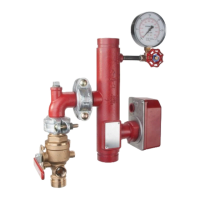
Optional
Pressure
Relief Trim
Installation
Model RM-1 commercial and resi-
dential riser manifold assemblies are
designed to accommodate an optional
pressure relief valve and trim compo-
nents (Ref. Figure 5).
Optional pressure relief trim must be
installed in accordance with the follow-
ing procedures.
Notes:
For assembly in Riser Manifolds
installed and in service, verify the fire
protection system is de-pressurized
and drained. Close the system supply
control valve, set commercial manifold
test and drain valve to DRAIN or open
residential drain valve to relieve resid-
ual pressure and drain system. Make
certain that drainage water will not
cause any damage or injury.
Refer to Care and Maintenance section
for other requirements when closing a
fire protection system control valve and
placing system in service.
Apply thread sealant or TEFLON tape
on all threaded connections, with the
exception of internally sealed flexible
hose connections.
Commercial Manifolds
Refer to Figure 1 for commercial riser
manifold features and Figure 5 for pres-
sure relief trim components described
in this procedure.
Step 1. Remove 1/2 in. pipe plug from
manifold tee. Inspect exposed female
tee threads, remove thread sealant
remnants or debris as necessary.
Step 2. Install Pressure Relief Valve (1)
in manifold tee, orienting valve outlet
port perpendicular to and facing away
from manifold body.
Step 3. Install 1/2 in. x Close Nipple
(2) in pressure relief valve outlet port.
Step 4. Disconnect drain piping from
grooved outlet of manifold TD-1 test
and drain valve as applicable and install
Figure 323 Grooved Reducing Tee (4)
on valve outlet by securing with Fig-
ure 577 Grooved Coupling (5), align-
ing tee threaded branch outlet parallel
with pressure relief valve outlet port.
Reconnect drain piping to Figure 323
tee drain outlet as necessary.
Note: Refer to Technical Data Sheet
G901 for Figure 577 Grooved Coupling
installation and assembly instructions.
Step 5. Install Flexible Hose (3) by
threading female ends onto 1/2 in. x
close nipple installed on relief valve
outlet port and onto Figure 323 reduc-
ing tee branch outlet.
Note: Assure Flexible Hose is not sus-
ceptible to being caught or snagged by
other moving equipment.
Residential Manifolds
Refer to Figures 2, 3 or 4 for residen-
tial riser manifold features and Figure
5 for pressure relief trim components
described in this procedure.
Step 1. Remove 1/2 in. pipe plug from
manifold tee. Inspect exposed female
tee threads, remove thread sealant
remnants or debris as necessary.
Step 2. Install Pressure Relief Valve (1)
in manifold tee, orienting valve outlet
port perpendicular to and facing away
from manifold body.
Step 3. Disconnect drain piping from
threaded outlet of manifold drain valve
as applicable and install 1 in. x Close
Nipple (5) in valve outlet.
Step 4. Install Figure 815 Reducing
Tee (4) onto 1 inch x close nipple, align-
ing tee branch outlet parallel with pres-
sure relief valve outlet port. Reconnect
drain piping to Figure 815 tee drain out-
let as necessary.
Step 5. Install 1/2 in. x Close Nipples
(2) in pressure relief valve outlet port
and in Figure 815 reducing tee branch
outlet.
Step 6. Install Flexible Hose (3) by
threading female ends onto 1/2 in. x
close nipples installed on relief valve
outlet port and Figure 815 reducing tee
branch outlet.
Note: Assure Flexible Hose is not sus-
ceptible to being caught or snagged by
other moving equipment.
Residential Riser Manifolds
NO DESCRIPTION P/N
1 Pressure Relief Valve,
175 psi, 1/2” NPT ..........1001184-01
2 1/2” x Close Nipple, Qty 2 . . . 1001023-01
3 Flexible Hose, 1/2” x 16” . . . . 1001266-03
4 Figure 815 Threaded
Reducing Tee,
1” x 1” x 1/2” NPT .........1001259-07
5 1” x Close Nipple . . . . . . . . . . 1001025-01
Commercial Riser Manifolds
NO DESCRIPTION P/N
1 Pressure Relief Valve,
175 psi, 1/2” NPT ..........1001184-01
2 1/2” x Close Nipple ........1001023-01
3 Flexible Hose:
1-1/2 – 3 Inch (DN40 – DN80)
Size Manifolds,
1/2” x 24” ................1001266-02
4 – 6 Inch (DN100 – DN150)
Size Manifolds,
1/2” x 30” ................1001266-01
4 Figure 323 Reducing Tee,
Grooved x NPT Threaded:
1-1/2 – 3 Inch (DN40 – DN80)
Size Manifolds,
1-1/4” x 1-1/4” x 1/2”.......3231305GS
4 – 6 Inch (DN100 – DN150)
Size Manifolds,
2” x 2” x 1/2” .............3232005GS
5 Figure 577 Rigid Grooved
Coupling:
1-1/2 – 3 Inch (DN40 – DN80)
Size Manifolds,
1-1/4” ...................57713AGCP
4 – 6 Inch (DN100 – DN150)
Size Manifolds,
2” ......................57720AGCP
3
4
5
COMMERCIAL
RISER MANIFOLD
1
2
RESIDENTIAL
RISER MANIFOLD
1
2
5
4
2
FIGURE 5
MODEL RM-1 COMMERCIAL AND RESIDENTIAL RISER MANIFOLDS
OPTIONAL PRESSURE RELIEF TRIM INSTALLATION
 Loading...