Assembly
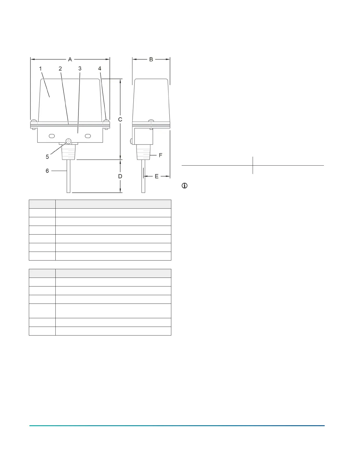
Figure 1: Components and dimensions
Callout Description
1 Cover
2 Gasket
3 Housing
4 Tamper resistant cover screw
5 Trip rod locking screw
6 Trip rod
Callout Dimension
A 4.55 in. (116 mm)
B 2.36 in. (60 mm)
C 5.04 in. (128 mm)
D Minimum: 0.50 in. (13 mm); Maximum: 2.00
in. (51 mm)
E 1.65 in. (42 mm)
F 1/2 in. NPT
Technical Data
Approvals
• UL and cUL Listed
• FM Approved
• CE
Contact ratings
• 10 A at 125/250 VAC
• 2.5 A at 30 VDC Resistive
Operating temperature range
• -40°F to +140°F (-40°C to +60°C)
Dimensions
• See Assembly section
Physical characteristics
Cover Die-cast finish, powder coat
Base Die-cast finish
Note: All components have corrosion resistant
finishes.
Operation
The switch mounts on a ½ in. NPT threaded hole in the
post indicator housing. The switch is a spring loaded
device. In the normal condition (valve fully open) the trip
rod is pushing against the valve actuator. As the indicator
valve closes, the valve actuator moves away from the trip
rod of the switch. The internal spring moves the trip rod
over and trips the switch.
Model TIP Indicator Post Supervisory Switch APAC Only2