Care and maintenance
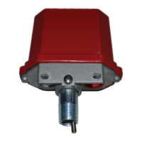
The TYCO Model TIP Indicator Post Supervisory Switch
must be maintained and serviced in accordance with
this section, in addition to any specific requirements of
the NFPA, and any impairment must be immediately
corrected. The inspection procedure must be performed
as described.
Before closing a fire protection system control valve for
inspection or maintenance work on the fire protection
system that it controls, permission to shut down the
affected fire protection system must first be obtained
from the proper authorities and all personnel who may
be affected by this action must be notified. After placing
a fire protection system in service, notify the proper
authorities and advise those responsible for monitoring
proprietary and/or central station alarms.
The owner is responsible for the inspection, testing,
and maintenance of their fire protection system and
devices in compliance with this document, as well as
with the applicable standards of the NATIONAL FIRE
PROTECTION ASSOCIATION such as NFPA 25, in addition
to the standards of any authority having jurisdiction (AHJ).
Contact the installing contractor or product manufacturer
with any questions.
It is recommended that automatic sprinkler systems
be inspected, tested, and maintained by a qualified
inspection service.
Inspecting the supervisory switch
Before you begin:
• The inspection procedure must be performed as
specified, in addition to any specific requirements of
the NFPA, and any impairment must be immediately
corrected.
• The operation of the supervisory switch and its
associated monitoring system must be tested upon
completion of installation.
• Test the switch periodically in accordance with
applicable NFPA codes and standards and/or the AHJ. A
quarterly arrangement is recommended.
To inspect the switch, complete the following steps:
1. Turn the valve operating mechanism towards the
the closed position. Verify the switch operates
within the first two revolutions.
2. Fully close the valve and verify the switch does not
reset.
3. Fully open the valve and verify the switch restores
to the normal condition.
Limited Warranty
For warranty terms and conditions, visit http://www.tyco-
fire.com.
Ordering Procedure
Contact your local distributor for availability. When
placing an order, indicate the full product name, and part
number (PN).
Indicator post supervisory switch
Specify: Model (see Table 2), Indicator post supervisory
switch, quantity, PN (see Table 2).
Table 2: Switch part numbers
Model Part number
TIP-1 300101
TIP-2 300103
© 2022 Johnson Controls. All rights reserved. All specifications and other information shown were current as of document revision and
are subject to change without notice.
www.johnsoncontrols.com

 Loading...