3-2. INSPECTION
Before and after disassembly,inspect each part
for the items mentioned below.Parts which
deviate from the specified values should be
replaced.
-Wash clean all disassembled parts and check them for
wear,damage,deformation,Burning ,etc. Defective parts
should be corrected or replaced.
-As the drive pinion and the ring gear make a pair,they
should be replaced together even if only one is found to
be defective.
-Backlash between the drive pinion and the ring gear
Backlash 0.1-0.2 mm
(0.004-0.008 in)
-Backlash between the diff-pinion and the dif-side gear.
Backlash 0.1-0.2 mm
(0.004-0.008 in)
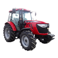
When the backlash exceeds 0.5mm,also inspect the
(1) Drive pinion
(2) Tapered roller bearing
(3) Drive pinion metal
(4) Tapered roller bearing
(5) Nut (M30X1.0)
(6) Gear
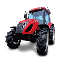
b.Be sure that the starting torque of
the drive pinion meets the specified
level.
Starting torque 8-11 Kgf.m
(0.08-0.11KN.cm)
Fig.5-30
When the backlash exceeds 0.5mm,also inspect the
thrust collar for wear,defective collars should be
replaced.
-Disengaging the resistance of PTO shifters.
Standard Value 18-22Kgf (40-49lbs)
Usable limit 17 Kgf (38 lbs)
* Measured at the shifter
3-3. REASSEMBLY
Reassemble the parts in reverse order of disassembly,
following these instructions.
(1) Ring gear,Drive pinion,and related parts.
a. Apply oil to the drive pinion and related parts
ahead of time.Then install them and tighten the
assembly to the specified torque.
Tightening torque 1.4Kgf.m (9.36 ft.lbs)
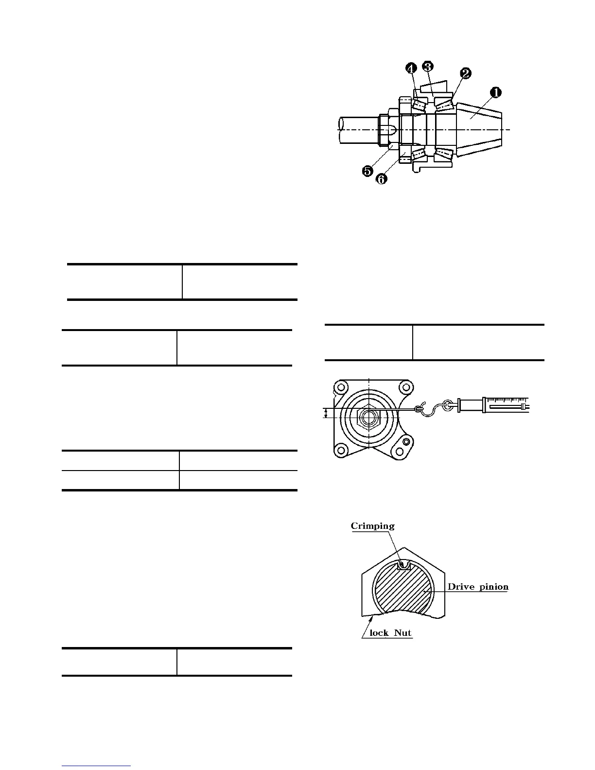
c.After the starting torque has been
adjusted to the specified level,crimp the
lock of the nut at one point as illustrated.
d. Tighten the drive pinion metal(support)
by providing it with the same shimming
thickness that it had when it was
disassembled.
5-19
Fig.5-31
Fig.5-32
 Loading...