9-6
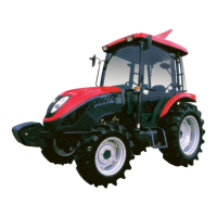
5) When assembling the lift crank on the lift
lift shaft,mesh their splines using the
alignment marks which were put their
before disassembly
Fig.9-13
Fig.9-14
Fig.9-15
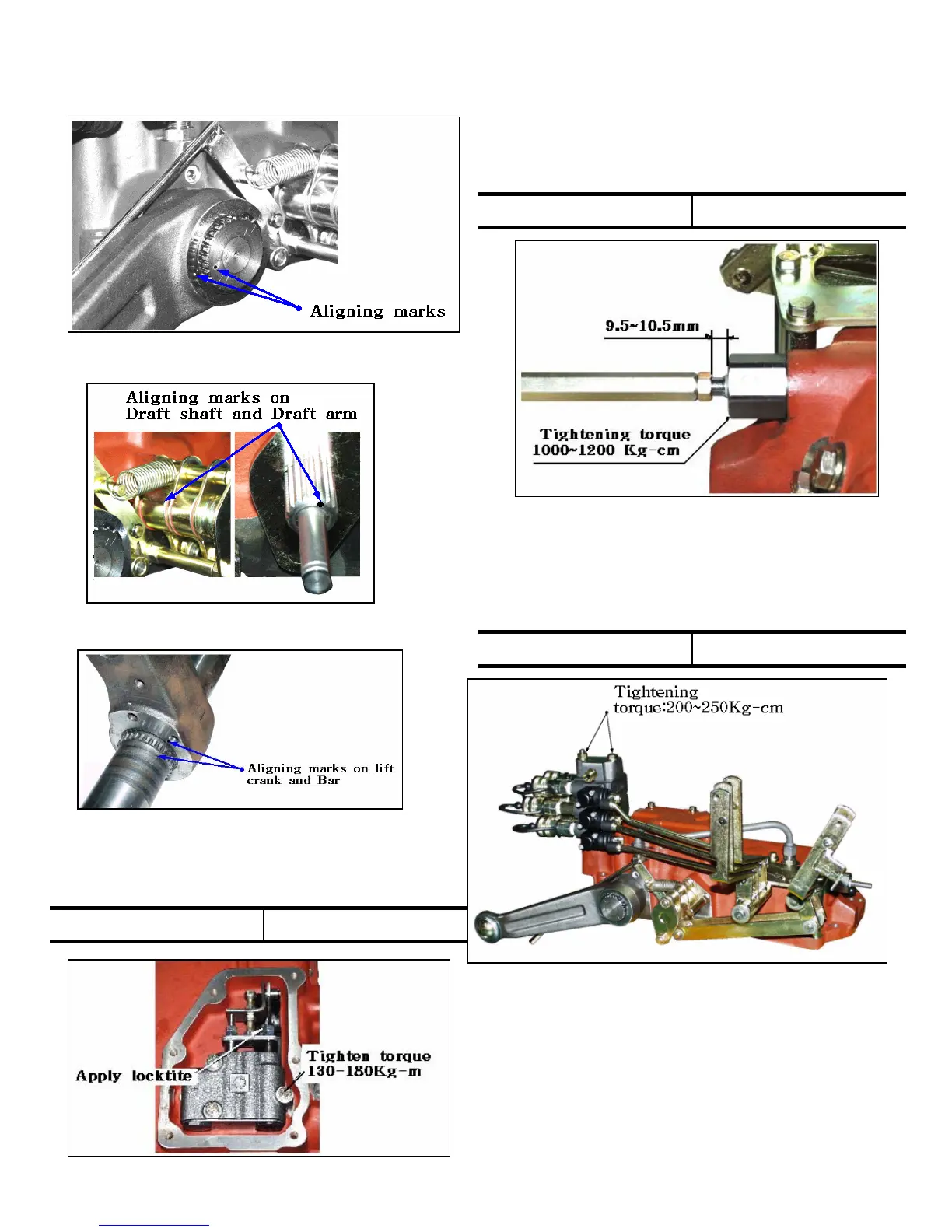
6) Tighten the Main valve securely to the
specified torque
Fig.9-16
130~180 Kg.cmTightening torque
7) When installing the control valve,apply grease
to the o-rings and avoid their dislocation or
binding during tightening the valve to the
specified torque
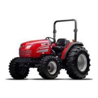
8) Tighten the slow return check valve to the
specified torque
Fig.9-17
1000~1200 Kg.cmTightening torque
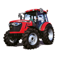
Fig.9-18
9) Tighten the Exterior valve(remote control valve)
to the specified torque
200~250 Kg.cmTightening torque
 Loading...