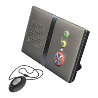
Fig1:Partsinthebox
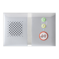
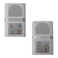
Fig2:Buttons,StatusLED&Connections
Fig3:TouchPendantWearingOptions
1.0Partsinthebox(seeFig1)
# Item
1 ReachIPAt‐HomeAlarmunit
2 ACAdapterincluding UK&EUmainsplugoptions
3 Connector CoverformountingtheReachIPflat
4 StandformountingtheReachIPvertically
5 ScrewforfixingtheStand orConnectorCover
6 TouchPendant&WearingOptions(neckcord/wriststrap/beltclip)
2.0Buttons,StatusLED&Connections(seeFig2)
# Function
RedAlarmButton:make anemergencycall
GreenCancelButton:cancelanemergencycallmadeinerror
YellowFunctionButton: toggleHome/Awaymode(ifenabled)
BlackPowerButton: on/offandenterControl Mode/ServiceMenu
StatusLED: off isnormal (Green nosignal,Red alarm,Amber fault)
SUPPLY
5VDCinputfromACAdapter
USB
ProgrammingPort (factoryuseonly)
ETHERNET
ConnectiontotheInternetviaaRouter (future upgrade)
3.0TouchPendantWearingOptions(seeFig3)
TheTouchPendantisaportablealarmtriggerthatcanbewornaroundtheneck,on
thewristorclippedtoabelt.ThePendantisalreadyregisteredtotheReachIPunit
andreadytouse,justfitthedesiredwearing
optionasdescribedbelow;
NeckCord:liethecordthroughoneofthegroovesontherearonthePendantthen
slidetheneckcordattachmentintoplace.Note:smallercordendmarkedinFig3.
WristStrap:feedthewriststrap(patternsideup)throughthe2slotsinthewrist
strapattachment.Note:locatethepipmarkedinthecentreholeinFig3.
Pushthealuminiumfixingstudthroughtheholemarkedattheendofthestrap.
BeltClip:simplyclipintoplaceontherearofthePendant.Note:thesuctioncupcan
befittedtothebeltcliptostickthePendanttoahardsurface,e.g.atiledwall.
3.1Setting‐uptheReachIPunit
1.PlugtheACAdapterintothemainssupply.
2.PlugtheACAdapterLeadintotheReachIPunitSUPPLYport.
3.Switchthemainssupplyonatthewall,pressandholdthePowerbuttonfora
coupleofsecondsuntil
the3frontbuttonsilluminatebrieflythenrelease.TheRed
Alarmbuttonwillremainlitifilluminationisenabled(default)andtheStatusLEDwill
belitgreenuntilaGSMsignalisestablishedthenitwillgoout.
4.IMPORTANT:rangetestthePendantfromallextremesofthe
home‐seesection4.4
5.MakeanalarmcalltotheAlarmReceivingCentre(ARC)tocheckoperation.
3.2MakinganAlarmCall
PresstheAlarmbuttonandtheunitwillannounce“callingforhelp‐pleasewait”
whenanalarmcallisbeingmade.TheAlarmbuttonwillflashred.Itispossibleto
cancelthealarmwithinthefirst5secondsbypressingthe
Cancelbutton.
4.0ControlMode&ServiceMenu
TheReachIPisnormallyinidlemode;ControlModeandServiceMenuarewaysof
easilyreconfiguringtheunit.Theunitwillreturntoidlemodeafterachangeismade
orafter5secondsofinactivity.
ControlModeFunctions
EnterControlModebypressingthePowerbuttononce,theunitwillbeepandthe
andbuttonswillilluminate.TheControlModefunctionsarelistedbelow;
# ControlModeFunctions
RedAlarmButton:toggleRedAlarmButtonillumination on/off
GreenCancelButton:changespeechandsounds volume
YellowFunctionButton:enterServiceMenu (seebelow)
ServiceMenuFunctions
OnceinControlMode,pressandholduntiltheunitannouncesthefirstService
Menufunction“addradiodevice”thenrelease,thebuttonwillbeflashing.Press
thebuttontosequentiallystepthroughthefunctions,pressthebuttontoselect
therequired
function.TheServiceMenufunctionsarelistedbelow;
# ServiceMenuFunctions
1 AddRadioDevice
2 RangeTestMode(alsoincludesGSMSignalStrengthMode)
3 DeleteRadioDevices
4 Home/AwayActivityFunction
4.1ToggleRedAlarmButtonIllumination
PressthePowerbuttontoenterControlModethenpressandholduntiltheunit
announcesthenewRedButtonstatee.g.iftheilluminationwasONthenitwill
announce“functionisdisabled”andilluminationwillnowbeoff,if
itwasOFFthenit
willannounce“functionisenabled”andilluminationwillnowbeon.
4.2ChangeSpeechandSoundsVolume
PressthePowerbuttontoenterControlModethenthenpressandholduntilthe
unitsoundsanumberofbeepstoindicateitsSPEECH
volumesetting‐continue
holdingtocyclethroughthe3settingsandreleaseontherequiredsetting.Press
andholdagainwithin5secondstochangetheSOUNDlevelsetting.
4.3AddRadioDevice
PressthePowerbuttontoenterControlModethenpressandholduntilthe
unit
announces“addradiodevice”thenrelease.Pressthebuttontoconfirmthen
activatetheradiodevice.Theunitwillsoundahighbeepifit’sanewdeviceand
announce“rangetestmode”‐presstoconfirm,orpresstosteptothenext
function,
orpresstoexitthemodeandtheunitwillannouncethenextfunction.
Note:ifthedevicealreadyexistsalowbeepwillsound.
4.4RangeTestMode
PressthePowerbuttontoenterControlModethenpressandholduntiltheunit
announces“addradio
device”thenrelease.Pressagainandtheunitwillannounce
“rangetestmode”thenpresstoconfirm.Theandbuttonswillbeflashing.
GotoallextremesofthehomeandpressthePendant,theReachIPwillrespondwith
abeepand
thePendantbuttonwillflashgreenifthesignalisreceived.Presstoexit
themodeandtheunitwillannouncethenextfunction.
ReachIP
At‐HomeAlarm
Screwfor
Stand/Cover
ACAdapterwith
UK&EUPlugs
TouchPendant&
WearingOptions
Connector
Cover
Stand
ReachIPunit
Red
AlarmButton
Green
CancelButton
Yellow
Function
Button
Status
LED
Touch
Pendant
NeckCord
Attachment
WristStrap