LEA-5, NEO-5, TIM-5H - Hardware Integration Manual
GPS.G5-MS5-09027-A2 Released Design-in
Page 44 of 68
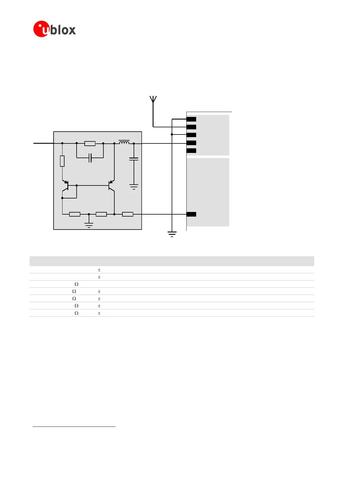
The open circuit detection circuit uses the current flow to detect an open circuit in the antenna. The threshold
current can be calculated using Equation 1.
GND
RF_IN
GND
V_ANT
VCC_RF
Active Antenna
ADDET_N
V_ANT
Antenna
Supply in
Analog GND
R1
R2
R3 R4 R5
T2
PNP
T1
PNP
C1
C2
FB1
AADET_N
u-blox 5 module
Figure 37: Schematic of open circuit detection variant B (for exact pin orientation see data sheet)
e.g. Murata BLM18HD601SN1
e.g. Philips Semiconductors
12
Table 10: Active antenna supervisor, bill of material
Status reporting
At startup and on every change of the antenna supervisor configuration the u-blox 5 GPS/GALILEO module will
output a NMEA ($GPTXT) or UBX (INF-NOTICE) message with the internal status of the antenna supervisor
(disabled, short detection only, enabled).
None, one or several of the strings below are part of this message to inform about the status of the active
antenna supervisor circuitry (e.g. “ANTSUPERV= AC SD OD PdoS”).
Transistors from other suppliers with comparable electrical characteristics may be used.
 Loading...

