PAGE 1 OF 3 1211 IH-2708
OPERATION
TECHNICAL DATA
WARNING! Operator must read and understand
instructions here and on truck prior to use.
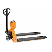
On the handle of the pallet truck, you will find the control
lever, which can be set in three positions.
(See Figure 1)
- LOWER = to lower the forks
- NEUTRAL = to move the load
- RAISE = to raise the forks
1. If the forks elevate while pumping in the NEUTRAL
position, turn the setting screw clockwise until
pumping the handle does not raise the forks and the
NEUTRAL position functions correctly.
2. If the forks descend while pumping in the NEUTRAL
position, turn the setting screw counter-clockwise until
the forks do not lower.
3. If the forks do not descend when the control lever is in
the LOWER position, turn the setting screw clockwise
until raising the control lever lowers the forks. Then
check the NEUTRAL position as per step 1 and 2.
4. If the forks do not lift while pumping in the RAISE
position, turn the setting screw counter-clockwise
until the forks elevate while pumping in the RAISED
position. Then check the NEUTRAL and LOWER position
as per steps 1, 2 and 3.
NOTE: When viewing the truck from the handle
side, the setting screw is located on the right
side of the pump above the right wheel. The
truck will lower faster or slower depending on
how far in or out the screw is adjusted.
Figure 1
H-2708, H-2900
H-3045
INDUSTRIAL
PALLET TRUCKS
MODEL H-2708/H-2900/H-3045
Capacity (Lbs) 5,500
Max. Fork Height (In) 7.5
Min. Fork Height (In) 3.0
Fork Length (In) 48
Width Overall Forks (In) 27
Fork Wheel Diameter (In) 3" Polyurethane
Steering Wheel Diameter (In) 7" Polyurethane
Net Weight (Lbs) 186