USER GUIDE
Wire Diagram 1
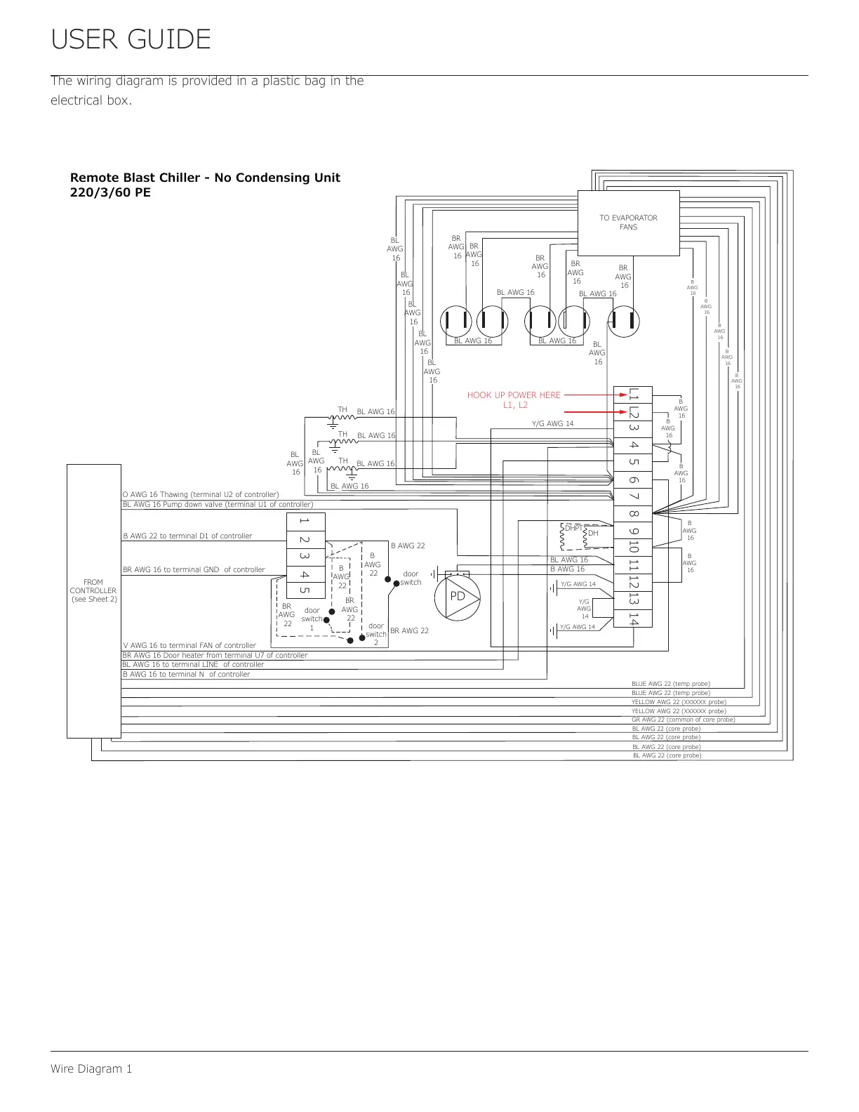
The wiring diagram is provided in a plastic bag in the
electrical box.
O AWG 16 Thawing (terminal U2 of controller)
FROM
CONTROLLER
(see Sheet 2)
HOOK UP POWER HERE
L1, L2
BL AWG 16 Pump down valve (terminal U1 of controller)
B AWG 22 to terminal D1 of controller
BR AWG 16 to terminal GND of controller
V AWG 16 to terminal FAN of controller
BR AWG 16 Door heater from terminal U7 of controller
BL AWG 16 to terminal LINE of controller
B AWG 16 to terminal N of controller
door
switch
B AWG 22
BR AWG 22
door
switch
2
door
switch
1
B
AWG
22
B
AWG
22
BR
AWG
22
BR
AWG
22
BL AWG 16
BL AWG 16
BL AWG 16
BL
AWG
16
BL
AWG
16
BL AWG 16
BL
AWG
16
BL
AWG
16
BL
AWG
16
BL
AWG
16
BL
AWG
16
BR
AWG
16
BR
AWG
16
BR
AWG
16
BR
AWG
16
BR
AWG
16
BL AWG 16
BL AWG 16
BL AWG 16
BL AWG 16
Y/G AWG 14
B
AWG
16
B
AWG
16
B
AWG
16
B
AWG
16
B
AWG
16
BLUE AWG 22 (temp probe)
BLUE AWG 22 (temp probe)
YELLOW AWG 22 (XXXXXX probe)
YELLOW AWG 22 (XXXXXX probe)
GR AWG 22 (common of core probe)
BL AWG 22 (core probe)
BL AWG 22 (core probe)
BL AWG 22 (core probe)
BL AWG 22 (core probe)
TO EVAPORATOR
FANS
TH
TH
TH
B
AWG
16
B
AWG
16
B
AWG
16
B
AWG
16
B
AWG
16
BL
AWG
16
DHPT
DH
BL AWG 16
B AWG 16
Y/G AWG 14
Y/G
AWG
14
Y/G AWG 14
PD
1 2 3 4 5
L1 L2 3 4 5 6 7 8 9 10 11 12 13 14
Remote Blast Chiller - No Condensing Unit
220/3/60 PE
43
 Loading...