USER GUIDE
System Diagnosis Guide
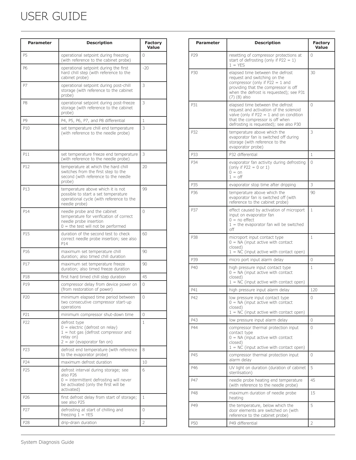
Parameter Description Factory
Value
P5 operational setpoint during freezing
(with reference to the cabinet probe)
0
P6 operational setpoint during the rst
hard chill step (with reference to the
cabinet probe)
-20
P7 operational setpoint during post-chill
storage (with reference to the cabinet
probe)
3
P8 operational setpoint during post-freeze
storage (with reference to the cabinet
probe)
3
P9 P4, P5, P6, P7, and P8 dierential 1
P10 set temperature chill end temperature
(with reference to the needle probe)
3
P11 set temperature freeze end temperature
(with reference to the needle probe)
3
P12 temperature at which the hard chill
switches from the rst step to the
second (with reference to the needle
probe)
20
P13 temperature above which it is not
possible to start a set temperature
operational cycle (with reference to the
needle probe)
99
P14 needle probe and the cabinet
temperature for verication of correct
needle probe insertion
0 = the test will not be performed
0
P15 duration of the second test to check
correct needle probe insertion; see also
P14
60
P16 maximum set temperature chill
duration; also timed chill duration
90
P17 maximum set temperature freeze
duration; also timed freeze duration
90
P18 rst hard timed chill step duration 45
P19 compressor delay from device power on
(from restoration of power)
0
P20 minimum elapsed time period between
two consecutive compressor start-up
operations
0
P21 minimum compressor shut-down time 0
P22 defrost type
0 = electric (defrost on relay)
1 = hot gas (defrost compressor and
relay on)
2 = air (evaporator fan on)
1
P23 defrost end temperature (with reference
to the evaporator probe)
8
P24 maximum defrost duration 10
P25 defrost interval during storage; see
also P26
0 = intermittent defrosting will never
be activated (only the rst will be
activated)
6
P26 rst defrost delay from start of storage;
see also P25
1
P27 defrosting at start of chilling and
freezing 1 = YES
0
P28 drip-drain duration 2
Parameter Description Factory
Value
P29 resetting of compressor protections at
start of defrosting (only if P22 = 1)
1 = YES
0
P30 elapsed time between the defrost
request and switching on the
compressor (only if P22 = 1 and
providing that the compressor is o
when the defrost is requested); see P31
(7) (8) also
30
P31 elapsed time between the defrost
request and activation of the solenoid
valve (only if P22 = 1 and on condition
that the compressor is o when
defrosting is requested); see also P30
0
P32 temperature above which the
evaporator fan is switched o during
storage (with reference to the
evaporator probe)
3
P33 P32 dierential 1
P34 evaporator fan activity during defrosting
(only if P22 = 0 or 1)
0 = on
1 = o
0
P35 evaporator stop time after dripping 3
P36 temperature above which the
evaporator fan is switched o (with
reference to the cabinet probe)
90
P37 eect caused by activation of microport
input on evaporator fan
0 = no eect
1 = the evaporator fan will be switched
o
1
P38 microport input contact type
0 = NA (input active with contact
closed)
1 = NC (input active with contact open)
1
P39 micro port input alarm delay 0
P40 high pressure input contact type
0 = NA (input active with contact
closed)
1 = NC (input active with contact open)
1
P41 high pressure input alarm delay 120
P42 low pressure input contact type
0 = NA (input active with contact
closed)
1 = NC (input active with contact open)
0
P43 low pressure input alarm delay 0
P44 compressor thermal protection input
contact type
0 = NA (input active with contact
closed)
1 = NC (input active with contact open)
0
P45 compressor thermal protection input
alarm delay
0
P46 UV light on duration (duration of cabinet
sterilisation)
5
P47 needle probe heating end temperature
(with reference to the needle probe)
45
P48 maximum duration of needle probe
heating
15
P49 the temperature, below which the
door elements are switched on (with
reference to the cabinet probe)
5
P50 P49 dierential 2
52
 Loading...