USER GUIDE
System Diagnosis Guide
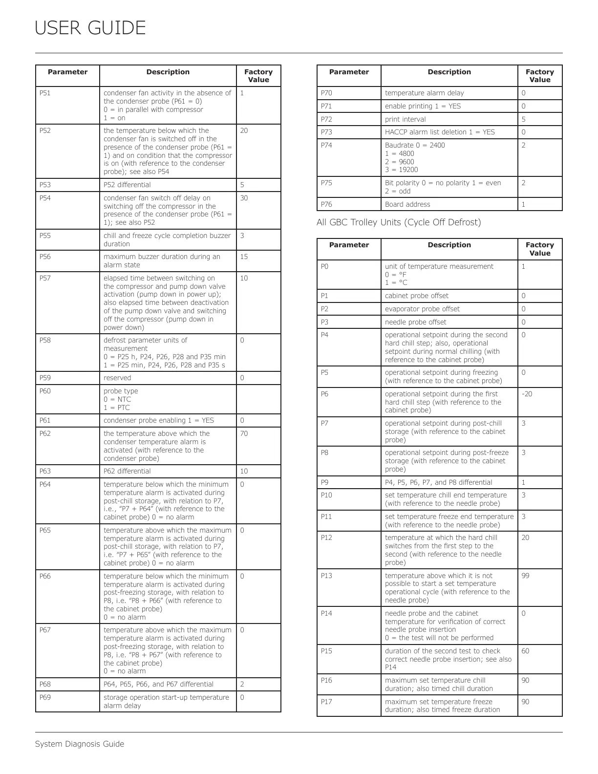
Parameter Description Factory
Value
P51 condenser fan activity in the absence of
the condenser probe (P61 = 0)
0 = in parallel with compressor
1 = on
1
P52 the temperature below which the
condenser fan is switched o in the
presence of the condenser probe (P61 =
1) and on condition that the compressor
is on (with reference to the condenser
probe); see also P54
20
P53 P52 dierential 5
P54 condenser fan switch o delay on
switching o the compressor in the
presence of the condenser probe (P61 =
1); see also P52
30
P55 chill and freeze cycle completion buzzer
duration
3
P56 maximum buzzer duration during an
alarm state
15
P57 elapsed time between switching on
the compressor and pump down valve
activation (pump down in power up);
also elapsed time between deactivation
of the pump down valve and switching
o the compressor (pump down in
power down)
10
P58 defrost parameter units of
measurement
0 = P25 h, P24, P26, P28 and P35 min
1 = P25 min, P24, P26, P28 and P35 s
0
P59 reserved 0
P60 probe type
0 = NTC
1 = PTC
P61 condenser probe enabling 1 = YES 0
P62 the temperature above which the
condenser temperature alarm is
activated (with reference to the
condenser probe)
70
P63 P62 dierential 10
P64 temperature below which the minimum
temperature alarm is activated during
post-chill storage, with relation to P7,
i.e., “P7 + P64” (with reference to the
cabinet probe) 0 = no alarm
0
P65 temperature above which the maximum
temperature alarm is activated during
post-chill storage, with relation to P7,
i.e. “P7 + P65” (with reference to the
cabinet probe) 0 = no alarm
0
P66 temperature below which the minimum
temperature alarm is activated during
post-freezing storage, with relation to
P8, i.e. “P8 + P66” (with reference to
the cabinet probe)
0 = no alarm
0
P67 temperature above which the maximum
temperature alarm is activated during
post-freezing storage, with relation to
P8, i.e. “P8 + P67” (with reference to
the cabinet probe)
0 = no alarm
0
P68 P64, P65, P66, and P67 dierential 2
P69 storage operation start-up temperature
alarm delay
0
Parameter Description Factory
Value
P70 temperature alarm delay 0
P71 enable printing 1 = YES 0
P72 print interval 5
P73 HACCP alarm list deletion 1 = YES 0
P74 Baudrate 0 = 2400
1 = 4800
2 = 9600
3 = 19200
2
P75 Bit polarity 0 = no polarity 1 = even
2 = odd
2
P76 Board address 1
All GBC Trolley Units (Cycle O Defrost)
Parameter Description Factory
Value
P0 unit of temperature measurement
0 = °F
1 = °C
1
P1 cabinet probe oset 0
P2 evaporator probe oset 0
P3 needle probe oset 0
P4 operational setpoint during the second
hard chill step; also, operational
setpoint during normal chilling (with
reference to the cabinet probe)
0
P5 operational setpoint during freezing
(with reference to the cabinet probe)
0
P6 operational setpoint during the rst
hard chill step (with reference to the
cabinet probe)
-20
P7 operational setpoint during post-chill
storage (with reference to the cabinet
probe)
3
P8 operational setpoint during post-freeze
storage (with reference to the cabinet
probe)
3
P9 P4, P5, P6, P7, and P8 dierential 1
P10 set temperature chill end temperature
(with reference to the needle probe)
3
P11 set temperature freeze end temperature
(with reference to the needle probe)
3
P12 temperature at which the hard chill
switches from the rst step to the
second (with reference to the needle
probe)
20
P13 temperature above which it is not
possible to start a set temperature
operational cycle (with reference to the
needle probe)
99
P14 needle probe and the cabinet
temperature for verication of correct
needle probe insertion
0 = the test will not be performed
0
P15 duration of the second test to check
correct needle probe insertion; see also
P14
60
P16 maximum set temperature chill
duration; also timed chill duration
90
P17 maximum set temperature freeze
duration; also timed freeze duration
90
53
 Loading...