USER GUIDE
System Diagnosis Guide
ALARM MESSAGE NOTES/CONSEQUENCES
DEFROSTING TIME The defrost process did not stop within
the maximum defrosting time. The
defrost ends by coil temperature (DTE).
If the stop does not happen within DTO
minutes, then the alarm triggers.
Check the evaporator coil icing status;
if one defrost is not enough, repeat the
defrost. If the alarm occurs during the
holding cycle, the problem may be with
the defrost device (hot gas valve). Using
the Blast Chiller as a holding cabinet for
too long may cause this alarm.
ELECTRICAL
FEEDING
The voltage supply is not within the
safety range. The parameter MRV Main
Reference Voltage determines the range
by plus or minus 20%. Check the voltage
actual reading from the Energy section
during a cycle. Call Service if low or high
voltage is suspected.
LOW TEMPERATURE Occurs during the holding cycle, if the
air temperature goes below the lower
temperature limit, parameter ALL. This
parameter is dierential to the setpoint.
HIGH
TEMPERATURE
Occurs during the holding cycle, if the
air temperature goes above the higher
temperature limit, parameter ALH. This
parameter is dierential to the setpoint.
AIR PROBE (S1) Air probe failure. Call Service.
EVAPORATOR
PROBE (S2)
Evaporator probe failure. Call Service.
CONDENSER PROBE (S3) (Not applicable in this version of
Blast Chiller) Condenser probe failure.
Call Service.
FOOD PROBE (PT1) Insert probe core 1 failure. Call Service.
FOOD PROBE (PT2) Insert probe core 2 failure. Call Service.
FOOD PROBE (PT3) Insert probe core 3 failure. Call Service.
FOOD PROBE (PT4) Insert probe core 4 failure. Call Service.
RELAY 1,2,…,8
BROKEN
The electronic board detected a failure on
Relay 1,2,…8. Call Service.
TRIAC BROKEN The electronic board detected a failure
on the PWM output for evaporator fan
variable speed. Call Service.
BLACK OUT The system recorded a power interruption
without switching o the display.
NOTE: This version of touch screen controllers
has no high/low pressure alarms.
The high/pressure switch will cut out
contactor coil for safety or pull down
purpose.
NOTE: Monitor correct communication between
display and power board from signals ext/
int on the left bottom side of the display.
Both signals blink “blue” if communication
is good. One or both blink “red” if an error
is occurs. Check the connection cable for
continuity.
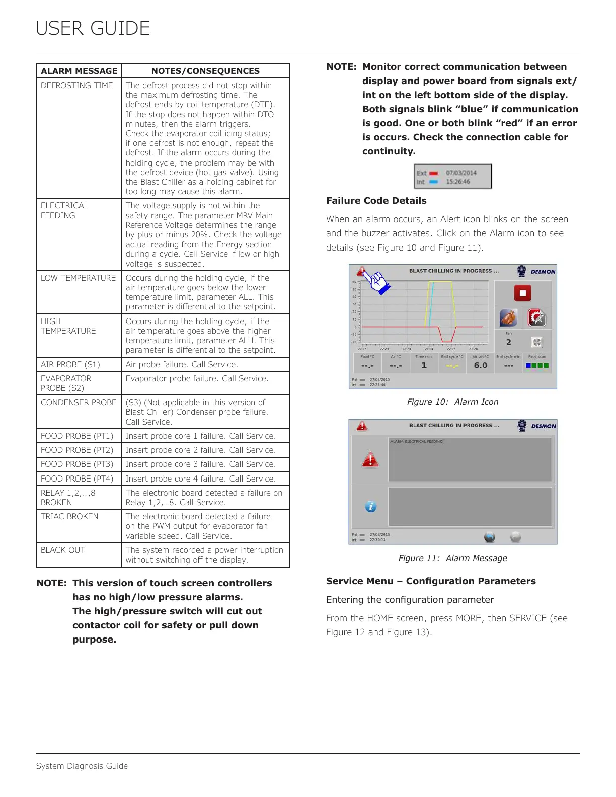
Failure Code Details
When an alarm occurs, an Alert icon blinks on the screen
and the buzzer activates. Click on the Alarm icon to see
details (see Figure 10 and Figure 11).
Figure 10: Alarm Icon
Figure 11: Alarm Message
Service Menu – Conguration Parameters
Entering the conguration parameter
From the HOME screen, press MORE, then SERVICE (see
Figure 12 and Figure 13).
58
 Loading...