MAX-M10S-Integration manual
The high and the low period of the output cannot be less than 50 ns, otherwise pulses can
be lost.
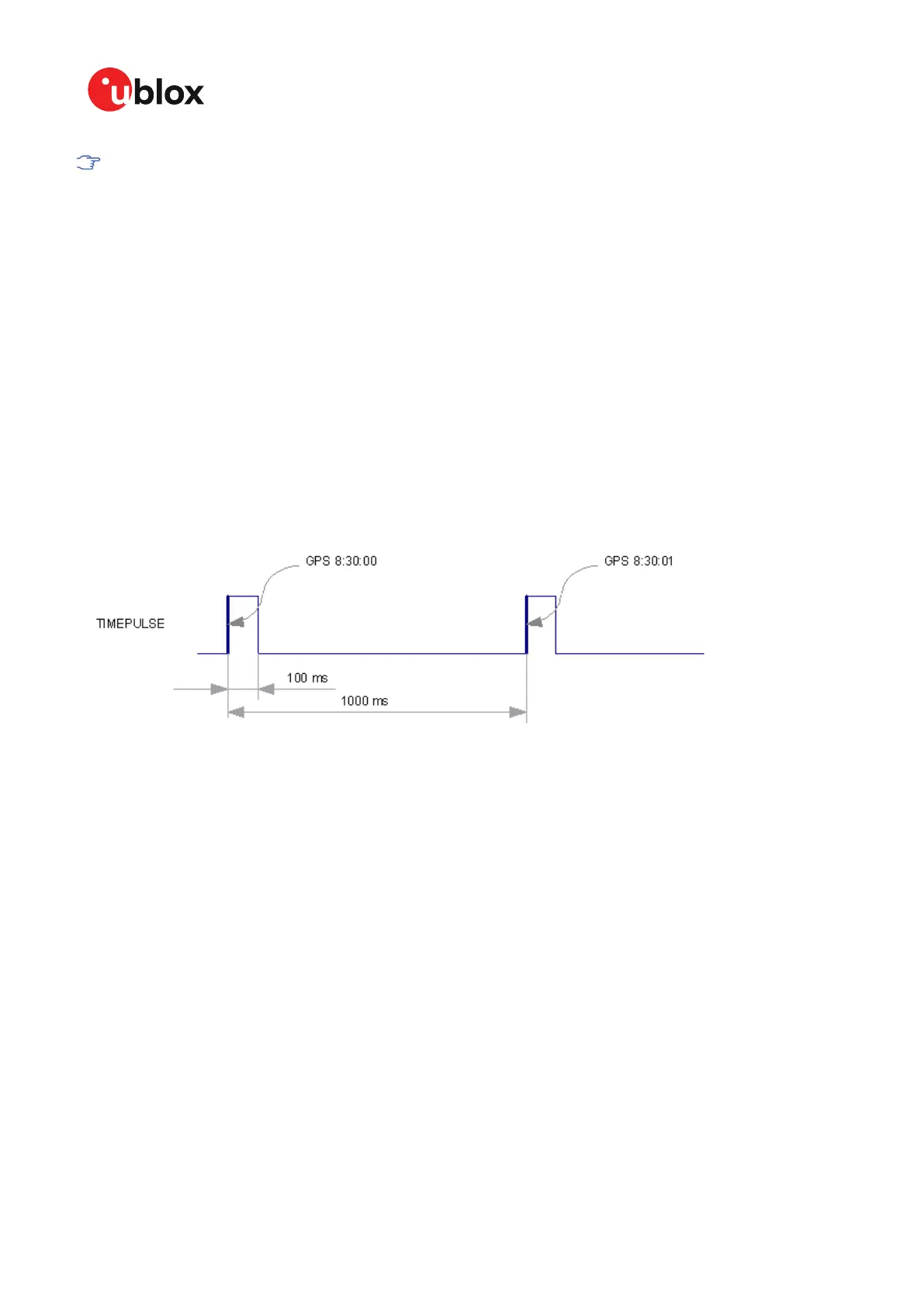
2.10.2.1 Example
The example below shows the 1PPS TIMEPULSE signal generated on the time pulse output
according to the specific parameters of the CFG-TP-* configuration group:
• CFG-TP-TP1_ENA = 1
• CFG-TP-PERIOD_TP1 = 1 000 000 µs
• CFG-TP-LEN_TP1 = 100 000 µs
• CFG-TP-TIMEGRID_TP1 = 1 (GPS)
• CFG-TP-PULSE_LENGTH_DEF = 0 (Period)
• CFG-TP-ALIGN_TO_TOW_TP1 = 1
• CFG-TP-USE_LOCKED_TP1 = 1
• CFG-TP-POL_TP1 = 1
• CFG-TP-PERIOD_LOCK_TP1 = 100 000 µs
• CFG-TP-LEN_LOCK_TP1 = 100 000 µs
The 1 Hz output is maintained whether or not the receiver is locked to GPS time. The alignment to
TOW can only be maintained when GPS time is locked.
Figure 18: Time pulse signal with the example parameters
2.11 Time maintenance
Maintaining accurate time can improve the speed and performance of the receiver restart. Estimate
of GNSS time can be maintained by a real-time clock, or it can be provided to the receiver by the host.
Estimate of the clock drift of the receiver local oscillator or an external reference frequency can also
be provided to improve the startup performance.
2.11.1 Real-time clock
The receiver contains a real-time clock (RTC). The RTC section is located in the backup domain and
can keep time while the receiver is otherwise powered off. When the receiver powers up, it attempts
to use the RTC to initialize receiver local time and in most cases this leads to considerably faster
and more accurate first fixes.
2.11.2 Time assistance
The host can deliver time assistance to the receiver using UBX-MGA-INI-TIME_UTC or UBX-MGA-
INI-TIME_GNSS for better startup performance.
The current GNSS time can be supplied to the receiver as a coarse value via the standard
communication interfaces. This method suffers from communication latency and unpredictable
UBX-20053088 - R03
2 Receiver functionality Page 49 of 89
C1-Public

 Loading...