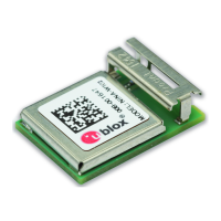
NINA-W1 series - User Manual
The VCC_IO connection must be as wide and short as possible.
The VCC_IO connection must be routed through a PCB area separated from sensitive analog
signals and sensitive functional units. It is a good practice to interpose at least one layer of PCB
ground between VCC_IO track and other signal routing.
There is no strict requirement of adding bypass capacitance to the supply net close to the module.
However, depending on the layout of the supply net and other consumers on the same net, bypass
capacitors might still be beneficial. Though the GND pins are internally connected, connect all the
available pins to solid ground on the application board, as a good (low impedance) connection to an
external ground can minimize power loss and improve RF and thermal performance.
3.3 Antenna interface
As the unit cannot be mounted arbitrarily, the placement should be chosen with consideration so
that it does not interfere with radio communication. The W1x6 modules with a PCB trace antenna
cannot be mounted in a metal enclosure. No metal casing or plastics using metal flakes should be
used. Avoid metallic based paint or lacquer as well.
3.3.1 On-board antenna design
If a plastic enclosure is used, it is possible to use NINA-W1 with the embedded antenna. In order to
reach an optimum operating performance, follow the instructions provided in the sections below.
3.3.1.1 NINA-W1x6 – PCB trace antenna
The module shall be placed in the center of an edge of the host PCB.
A large ground plane on the host PCB is a prerequisite for good antenna performance. It is recommended to have the
ground plane extending at least 10 mm on the three non-edge sides of the module. See
Figure.
The host PCB shall include a full GND plane underneath the entire module, with a ground cut out
under the PCB trace antenna according to the description in Figure .
The NINA-W1x6 has four extra GND pads under the antenna that need to be connected for a
good antenna performance. Detailed measurements of the footprint including this extra GND
pads can be found in the NINA-W1 series data sheets.
High / large parts including metal shall not be placed closer than 10 mm to the module’s antenna.
At least 10 mm clearance between the antenna and the casing is recommended. If the clearance
is less than 10 mm, the antenna performance can be adversely affected.
The module shall be placed such that the antenna faces outwards from the product and is not
obstructed by any external items in close vicinity of the products intended use case.
 Loading...