EasyManua.ls Logo

UDIAG CR800 - User Manual

UDIAG CR800
2 pages
Print Icon
To Next Page IconTo Next Page
Loading...
2. Before start diagnosis, please make sure
A
B
C
D
E
F
G
H
I
J
K
L
The ignition switch is
turned to ON position
Engine is off 10 to 14 volt vehicle power
Never try to provide power for the code reader from
USB connection when the code reader is
communicating with a vehicle.
Don’t connect or disconnect the equipments while
the ignition is on or the engine is running.
1
2 3
START
STOP
10-14V
Turn the ignition off.
Locate the data link connector (DLC) under the
dash on the driver side of the vehicle.
- 1 -
CR800 User Manual
3. Powering up the scanner
Before using the code reader, make sure to provide power to the code reader.
The unit operates on any of the following sources:
3.1. USB connection to computer
Application platform :
win 98 to win 10
3.2. 12-volt vehicle power
- 2 -
USB
a
b
1. Diagnostic operation
START
STOP
START
STOP
Switch the ignition key to the ON position. The code reader automatically boots up.
c
d
START
NEAR
CENTER
OF DASH
A
B
C
D
E
F
G
H
I
J
K
L
OBDII Cable
Green LED Display
Yellow LED Display
Red LED Display
I/M Key
VIN Key
DTC Key
UP Key
DOWN Key
BACK Key
HELP Key
ENTER Key
Provides communication for vehicle DLC.
Indicates the engine system is working normally.
Shows the tool finds a possible problem.
Indicates there are some problems in one or more of the
vehicles systems.
Quick checks state emissions readiness and drive cycle
verification.
Quick checks the VIN code of vehicle.
Quick checks the DTC code.
Scroll the menu.
Scroll the menu.
Cancels an action and returns to previous screen or level.
Accesses to the Help function and it is also used to update
the code reader when long pressed.
Confirms an action or movement and moves to next level.
Question and Answer IconNeed help?

Do you have a question about the UDIAG CR800 and is the answer not in the manual?

Summary

Diagnostic Operation and Controls

Diagnostic Interface Components

Details the OBDII cable and indicator lights for system status.

Control Button Functions

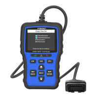
Explains the functionality of various control buttons for navigation and operation.

Pre-Diagnosis Checks and Precautions

Ignition and Power Requirements

Ensures correct ignition state and vehicle power supply before diagnosis.

Usage Precautions

Important warnings regarding power connection during operation and ignition state.

Powering Up the Scanner

USB Connection to Computer

Connects the scanner to a computer via USB for power.

12-Volt Vehicle Power

Powers the scanner using the vehicle's 12V power source.

Software Update Procedure

Download and Preparation

Instructions for downloading the updater and preparing for the update process.

Update Process Steps

Step-by-step guide for connecting the scanner and initiating the update.

Print Test Results

Connecting and Printing

Connects the scanner to a computer and guides through printing test results.

Battery Function

Service and Support

Warranty and Service

UDIAG CR800 Specifications

General IconGeneral
BrandUDIAG
ModelCR800
CategoryDiagnostic Equipment
LanguageEnglish