Do you have a question about the UE 100 Serie and is the answer not in the manual?
Provides essential general information and safety precautions before installing and operating the pressure switch.
Details mounting instructions and wiring procedures, including tool requirements and electrical safety precautions.
Explains how to adjust the set point for H100 and H100K models using the internal adjustment screw.
Covers the set point adjustment procedure for models with internal adjustment wheels for differential pressure.
Describes the operation of manual reset buttons on specific control types, including how they latch and reset.
Step-by-step instructions for setting the switch gap, involving plunger and adjustment screws.
Provides physical dimensions and NPT connection sizes for various pressure switch models.
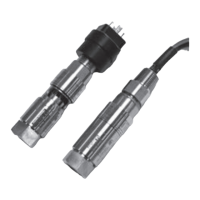
Details dimensions for temperature sensors, including immersion stem and bulb/capillary types.
Illustrates dimensions and connection types for differential pressure switch models.
Key guidelines for safe installation, operation, and maintenance to avoid unit damage and system issues.
Outlines the manufacturer's warranty terms, coverage period, and exclusions for product defects.
Defines the seller's liability limitations concerning product use, including consequential damages.
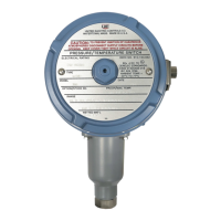
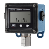
Introduces the 100 Series as a versatile, rugged switch for process and OEM equipment.
Covers storage/ambient temperature limits, repeatability, shock, vibration, and enclosure ratings.
Details switch output type, electrical ratings, weight, and electrical connection specifications.
Provides information on pressure connection types, temperature assembly, fill types, and deadband.
Lists UL, CE, and other compliance standards relevant to the pressure and temperature switches.
Presents a chart detailing adjustable set point ranges, deadband, and pressure ratings for pressure models.
Continues the pressure model specifications, including material options and connection types.
Specifications for pressure models utilizing bellows and piston designs, with range and deadband data.
Details specifications for differential pressure models, including diaphragm types and pressure ranges.
Lists specifications for B100 and C100 temperature models, including stem/bulb sizes and ranges.
Details specifications for E100 and F100 temperature models with bulb and capillary sensors.
Step-by-step guide to selecting Type, Model, and Options to build the correct part number.
Explains various switch option codes for features like gold contacts, DPDT, and adjustable deadband.
Lists miscellaneous options such as status lights, ATEX compliance, mounting brackets, and special cleaning.
Details alternative sensor materials for 'wc range models, affecting wetted parts and compatibility.
Specifies optional materials for wetted parts to handle corrosive media, including Hastelloy and Monel.
Describes available flush mount flange options for specific models, including size and rating details.
Lists available union connector options for temperature models, specifying brass and stainless steel types.
Details thermowell options for bulb and capillary switches, including material and length specifications.
Describes immersion stem options, including special construction and associated thermowell choices.
Provides information on optional immersion stem and capillary lengths, and protective options.
Visual representation of pressure sensor dimensions and NPT connection sizes for various models.
Illustrations of temperature sensor dimensions for immersion stem and bulb/capillary types.
Diagrams showing dimensions for differential pressure sensor models, including connection types.
Lists contact information for United Electric Controls sales offices across various regions in the United States.
Provides contact details for United Electric Controls' international sales offices in key global regions.