EasyManua.ls Logo

UE 120 Series User Manual

UE 120 Series
6 pages
To Next Page IconTo Next Page
Page #1 background imageLoading...
Page #1 background image
EXPLOSION-PROOF SEALING FITTINGS FOR ELEC-
TRICAL WIRE ENTRY. DO NOT MOUNT UNIT IN
AMBIENT TEMPERATURES LOWER THAN -40°F
(40°C) OR HIGHER THAN 160°F (71°C).
Types J120, J120K, H121, H121K, H122,
H122K, H122P
Mount controls vertically (pressure connection facing
down, See Figure 1a) or horizontally (electrical condui
facing up, See Figure 1b). Either mounting position will
properly orient the venting system. Control may be
surface mounted via the four 1/4” screw holes on the
enclosure or mounting bracket. It can also be mouned
directly to a rigid pipe using the pressure connection.
Types J120K, H121K, H122K Opposed Sensor
Differential Pressure Models 36-39, (S)147(B)-(S)157 (B),
367
“Opposed sensor” differential pressure controls should
be mounted with their pressure connection in the
horizontal position (See Figure 2). This will properly ori-
ent the vent holes on the pressure housing as well as
the 1/4” NPT venting conduit at the bottom of the third
compartment (standardly supplied with plastic plug.
GENERAL
MISUSE OF THIS PRODUCT MAY CAUSE
EXPLOSION AND PERSONAL INJURY.
THESE INSTRUCTIONS MUST BE THOR-
OUGHLY READ AND UNDERSTOOD BEFORE
UNIT IS INSTALLED.
The 120 Series pressure and differential pressure
controls are actuated when a bellows, diaphragm or
piston sensor responds to a pressure change. This
response at a pre-determined set point(s) actuates
a SPDT, dual SPDT or DPDT snap-acting
microswitch(es), which converts the pressure signal
into an electrical signal. Control set point(s) may be
varied by turning the internal adjustment hex (J120
models) or the external knob and pointer(s) (H121,
H122, H122P models) according to the procedures
outlined below.
PROOF PRESSURE LIMITS STATED IN THE
LITERATURE AND ON NAMEPLATES MUST
NEVER BE EXCEEDED, EVEN BY SURGES IN
THE SYSTEM. OCCASIONAL OPERATION OF UNIT
UP TO MAXIMUM PRESSURE IS ACCEPTABLE (E.G.
START-UP, TESTING). CONTINUOUS OPERATION
SHOULD NOT EXCEED THE DESIGNATED OVER
RANGE PRESSURE.
Proof Pressure
The highest pressure to which a sensing element may
be occasionally operated without adversely affecting
setpoint calibration and repeatability.
TOOLS NEEDED
Screwdriver
Adjustable Wrench to 1
1
2"
MOUNTING
ALWAYS HOLD A WRENCH ON THE
PRESSURE HOUSING HEX WHEN MOUNT-
ING UNIT. DO NOT TIGHTEN BY TURNING
ENCLOSURE. THIS WILL DAMAGE SENSOR AND
WEAKEN SOLDER OR WELDED JOINTS.
INSTALL UNITS WHERE SHOCK, VIBRA-
TION AND TEMPERATURE FLUCTUATIONS
ARE MINIMAL. ORIENT UNIT TO PREVENT
MOISTURE FROM ENTERING THE ENCLOSURE.
IT IS IMPERATIVE TO USE PROPERLY RATED
UNITED ELECTRIC
CONTROLS
Installation and Maintenance
Instructions
Please read all instructional literature carefully and thoroughly before starting. Refer to the final page for the listing of
Recommended Practices, Liabilities and Warrantees.
UL listed, CSA Certififed,
FM approved (option M415*)
Class I, Division 1, Groups B*, C, D
Class II, Division 2, Groups E, F, G
Class III
*NOTE: CSA, Class I, Division 1, Group B does not apply
to controls with option code 1530 or M450
**Not available with M450
CENELEC approved (Prefix “Q”)
EN50 014 and EN50 018
EEX d IIC T6
Part I - Installation
Potted Conduit
Connection
Breather Drain
(facing down)
Vent Holes
Figure 1a: H121, H121K, H122,
H122K, H122P
120 Series
Explosion-Proof Pressure
and Differential Pressure
Switches
Potted Conduit Connection
Breather Drain (facing down)
Figure 1b: J120, J120K
1/4” NPT
Vent Hole
Vent Holes
Question and Answer IconNeed help?

Do you have a question about the UE 120 Series and is the answer not in the manual?

UE 120 Series Specifications

General IconGeneral
BrandUE
Model120 Series
CategorySwitch
LanguageEnglish

Summary

General Information

Proof Pressure Definition

Defines the maximum occasional operating pressure without affecting setpoint calibration.

Installation Procedures

Mounting Instructions

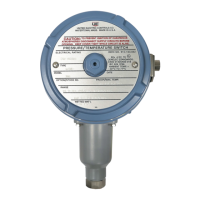
Covers general mounting, specific types (J120, H121, etc.), and opposed sensor models.

Tools Needed for Installation

Lists tools like screwdriver and adjustable wrench required for installation.

Wiring Instructions

Covers disconnection, wire size, torque, and electrical ratings.

Adjustment Procedures

Tools Needed for Adjustments

Lists tools like screwdriver and wrenches for adjustment procedures.

Adjustable Plunger Feature

Explains the two-piece adjustable plunger and when not to disturb it.

Set Point Adjustment for J120/J120K Models

Details set point adjustment for J120/J120K and J120K (36-39, etc.) models.

Set Point Adjustment for H121/H121K Models

Describes adjusting set point using external knob and pointer.

Set Point Adjustment for H122/H122K Models

Details independent or combined setting of microswitches for H122/H122K.

Special Adjustment Options

Explains adjustable deadband switch, manual reset, and span adjustment for M210.

Microswitch Gapping Procedure

Step-by-step guide for gapping microswitches using specific tools.

Gapping Procedure Model Specifics

Provides specific gapping instructions (flats turn) for models 680, 183-189, 270, etc.

Replacement Procedures

Tools Needed for Replacements

Lists tools like screwdrivers and wrenches for replacement procedures.

Safety Warning for Replacements

Emphasizes disconnecting electrical supply before removing explosion-proof cover.

Single Switch Replacements

Steps for replacing single microswitches in J120, J120K, H121, H121K models.

Dual Switch Replacements

Detailed steps for replacing dual microswitches in H122, H122K models.

H122P Switch Replacements

Steps for replacing switches in H122P models, noting differences between front/rear switches.

Product Dimensions

Set Point Adjustment Dimensions

Provides dimensional data for internal and external set point adjustment types.

Mounting Bracket Dimensions

Shows dimensions and mounting hole details for the M449 bracket.

Pressure Connection Dimensions

Illustrates pressure connection sizes (NPT) for various models.

Differential Pressure Connection Dimensions

Shows differential pressure connection sizes (NPT) for specific models.

Sanitary Fitting Dimensions

Displays dimensions for 2" and 1 1/2" sanitary fittings.

Model-Specific Connection Dimensions

Details pressure port dimensions for various models.

Recommended Practices and Warnings

General Installation and Operation Warnings

Advises on proof pressure limits, backup units, range selection, shock, vibration, and moisture.

Electrical Safety and Ratings

Stresses electrical ratings, wire codes, and using factory parts.

Limited Warranty Information

Outlines the limited warranty period and UE's obligations.

Liability Limitation

Limits seller's liability for damages and consequential losses.

Related product manuals