Remove cover and wire control (See Figure 3).
Replacing cover hand tight (a minimum of 5 full
threads engaged) is sufficient to maintain proper
protection. Additional tightening is required to fully
engage cover O-ring and seal enclosure to rain-
tight protection.
TOOLS NEEDED
Screwdriver
5/8” Open End Wrench
5/64” Allen Wrench
SOME MODELS HAVE A TWO-PIECE
ADJUSTABLE PLUNGER. THIS FEATURE
IS CHARACTERIZED BY A 3/16” HEX HEAD
SCREW INSTALLED IN THE PLUNGER. THE
LENGTH OF THIS ASSEMBLY IS ADJUSTED AT
OUR FACTORY AND IS CRITICAL TO THE FUNC-
TION OF THE CONTROL. DURING NORMAL
ADJUSTMENT, THESE COMPONENTS SHOULD
NOT BE DISTURBED. HOWEVER, WHEN
REPLACING THE ELECTRICAL SWITCH, IT MAY
BE NECESSARY TO ADJUST THE PLUNGER
LENGTH IN ORDER TO “RE-GAP” THE SWITCH.
REFER TO INSTRUCTIONS IN PART III -
REPLACEMENTS TO DETERMINE IF REGAPPING
IS NECESSARY.
AFTER COMPLETING ADJUSTMENTS ON
TYPE H121 AND H122 CONTROLS, BE
SURE TO RE-INSTALL ADJUSTMENT COVER. DO
NOT OVER TIGHTEN COVER SCREWS.
For set point adjustment and re-calibration, connect
control to a calibrated pressure source.
Types J120 (All) and J120K Models 455-559
Remove cover. Loosen slotted screw adjustment
lock. Adjust set point by turning 5/8” hex adjustment
screw clockwise (IN) to raise set point, or counter-
clockwise (OUT) to lower set point. Secure
adjustment screw by tightening adjustment lock
(see Figure 4a). Internal reference scales are
provided to show at which portion of the range (high
or low) the control is set. Re-calibration of models
50-55, S50B-S55B, 171-174, 183-189, 190-194,
471-474, 483-489, 490-494, 540-567, 680 & 701-
705 may also require the “re-gapping” of the space
between the top of the plunger and the bottom of
the microswitch. Use the flats on the plunger and
plunger hex screw as reference and follow the
gapping instructions on page 3.
Type J120K
Models 36-39,147-S157B, & 367
Remove front cover and gasket from sensor
assembly located below enclosure by unscrewing 4
slotted screws. Loosen slotted screw adjustment
lock (see Figure 4b). Adjust set point by turning
5/8” hex screw clockwise (IN) to increase setting or
counterclockwise (OUT) to decrease setting.
Adjusting screw should be locked by tightening
adjustment lock.
Controls with Breather Drain (Option M450)
Type J120, J120K Models 455-559
Mount with breather drain facing down and conduit con-
nection facing up (See Figure 1b). The conduit connec-
tion must be “potted” for this type of installation.
Types H121, H122 & H122P, All Models
Mount in vertical position with pressure assembly and
breather drain facing down (See Figure 1a).
WIRING
DISCONNECT ALL SUPPLY CIRCUITS
BEFORE WIRING UNIT. WIRE UNITS
ACCORDING TO NATIONAL AND LOCAL
ELECTRICAL CODES. MAXIMUM RECOMMENDED
WIRE SIZE IS 14 AWG. THE RECOMMENDED
TIGHTENING TORQUE FOR FIELD WIRING TERMI-
NALS IS 7 TO 17 IN-LBS.
ELECTRICAL RATINGS STATED IN LITERA-
TURE AND ON NAMEPLATES MUST NOT BE
EXCEEDED—OVERLOAD ON A SWITCH CAN
CAUSE FAILURE ON THE FIRST CYCLE.
TO PREVENT SEIZURE OF ENCLOSURE
COVER, DO NOT REMOVE LUBRICANT
(PETROLATUM). THREADS SHOULD ALSO
BE FREE OF DIRT, ETC.
Part II - Adjustments
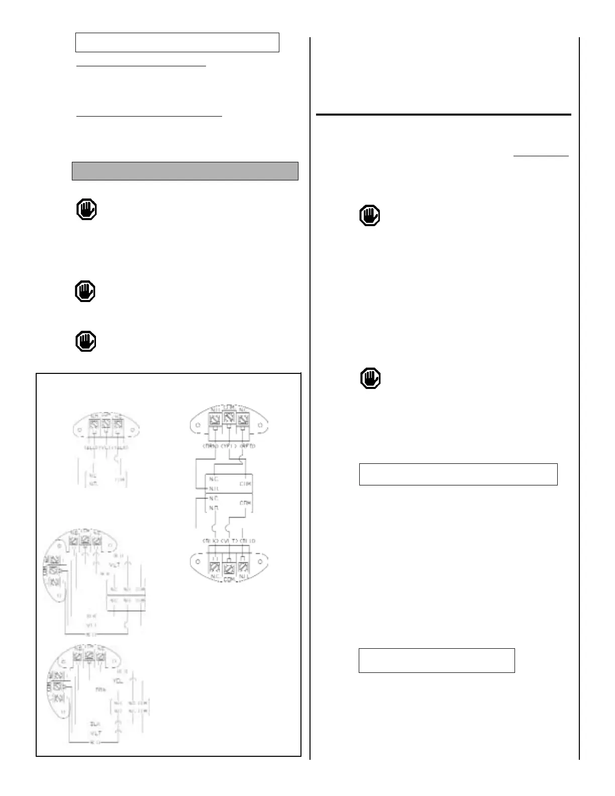
Figure 3
Use 75°C copper
conductors only.
Recommended
tightening torque for
field wiring terminals
is 7-17 in-lbs.
Option 1010,
Type J120
Types H121, J120,
H121K, J120K
Types H122,
H122K
HIGH
TERMINAL
BLOCK
HIGH SET
(BACK)
LOW SET
(FRONT)
LOW
TERMINAL
BLOCK
Option 1180,
Type H122P
 Loading...