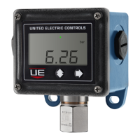
Types H121, H121K
Adjust set point by turning external knob and pointer
to desired setting on scale. Re-calibration (adjusting
set point after replacing microswitch): Slowly turn
adjustment knob until microswitch transfers.
Compare microswitch transfer point to actual pres-
sure. If they do not agree, loosen set screws on
adjustment knob with allen wrench and align pointer
to indicate actual pressure. Tighten knob set screws.
Types H122, H122K
Individual microswitches may be set together or apart
by up to 100% of range. When not set together, the
front microswitch can not be set higher than the rear
microswitch. Turning external knobs will increase or
decrease each switch setting independently. To
re-calibrate, follow procedure for Types H121 above
for each microswitch.
Controls with Options:
Option 1519, Adjustable Deadband Switch
This microswitch has an integral adjustment wheel.
Turning this wheel raises and lowers the pressure
rise set point. The fall set point remains constant.
Consult factory for additional information.
Type J120, Option 1530, Manual Reset
This microswitch, when actuated, remains actuated
until the pressure drops sufficiently to allow the reset
knob (located on the left side of the control) to be
manually turned to reset the microswitch.
Option M210 Indicator for
Differential Pressure Controls, Span Adjustment
(See Figure 5). To adjust indication for maximum
accuracy at any desired set point, follow steps 1 thru
4 listed below.
1) Remove front window and gasket (four screws)
to gain access to span adjustment.
2) Connect control to calibrated gauges and set
required differential pressure.
3) Using a screw driver, slowly turn the span
adjustment to obtain required indication
(See Figure 4).
4) Remount the front gasket and window.
Types H122P
Individual switches may be set together or apart by
up to 60% of range. The front switch is set by turning
the internal calibrating screw to the right for lower set
point and turning to the left for higher set point.
Figure 4a Figure 4b
J120K: Opposed Sensor,
Models 36-39, 147-157,
S147B, S157B, 367
Adjust Screw
Adjust Lock
When not set together, the front switch can not be set
higher than the rear switch. Turning the external
knob will increase or decrease each switch setting
simultaneously without disturbing their relationship.
NOTE: Spanning adjustment will not effect the mid-
range indication. The adjustment is factory calibrated
and sealed to indicate tampering.
DO NOT FORCE SPAN ADJUSTMENT,
SINCE PERMANENT DEFORMATION OF
THE LINKAGE MECHANISM MAY RESULT.
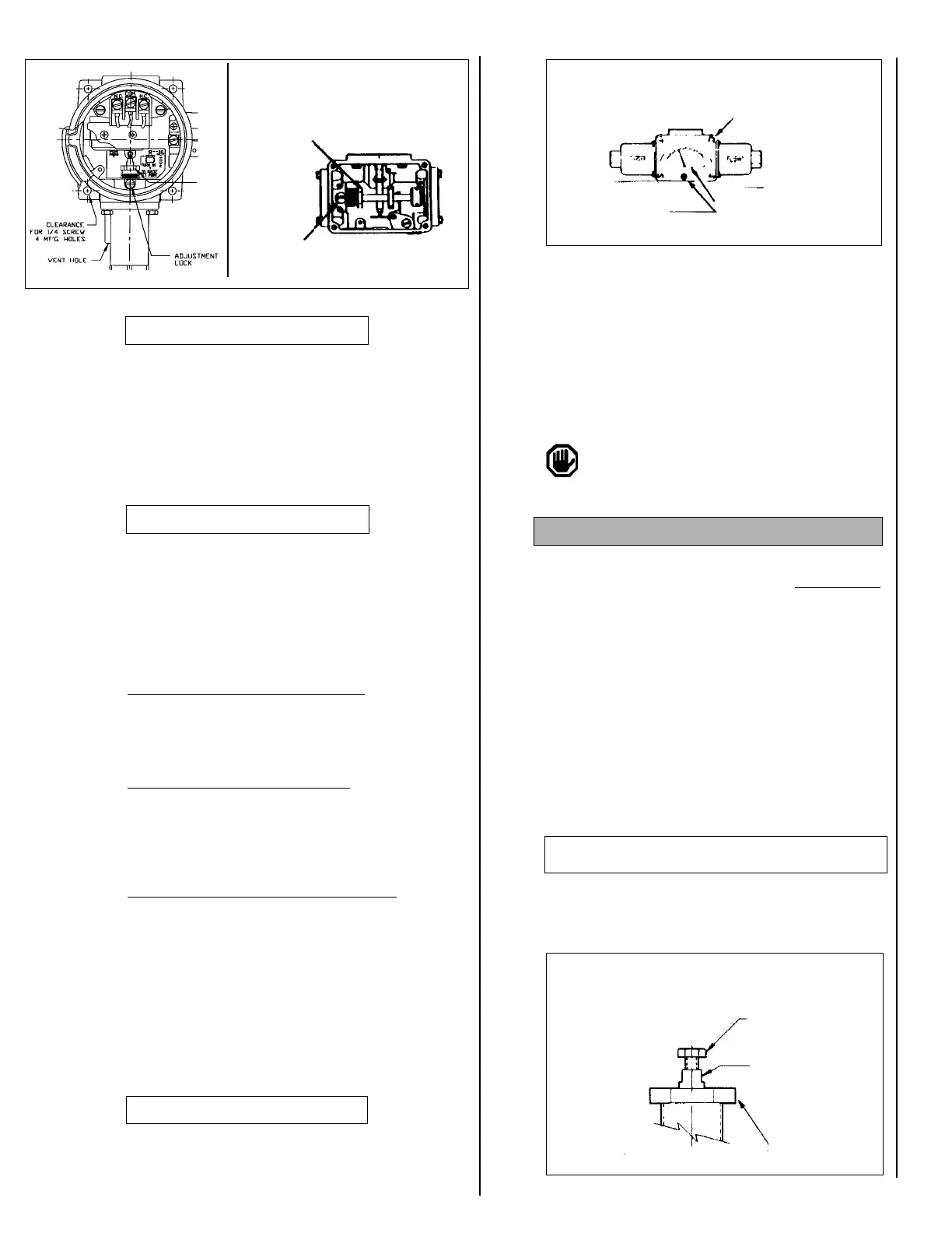
GAPPING PROCEDURE
TOOLS NEEDED
5/8” Open End Wrench
3/16” Open End Wrench (2)
1) Loosen adjustment lock.
2) Turn 5/8” hex adjustment screw IN, to approxi-
mately mid-range. This puts a load on the
sensor and exposes the plunger flats.
3) Using a 3/16” wrench on the plunger flats and a
3/16” wrench on the plunger hex screw, turn hex
OUT from plunger until microswitch actuates. If
microswitch has already actuated, turn plunger
hex screw IN until microswitch deactuates.
4) Continue per following instructions, depending
on model.
Models 50-55, S50B-S55B, 171-174 and 471-474,
521-525, 531-535, 540-548
Turn hex (IN) an additional 2 flats from this point
(approximately 1/3 turn). This will provide a
9-11 mil gap.
Figure 5
Adjustment Procedure for J120/J120K
Figure 6
Window Plexiglass
Span Adjust Screw
Window Mounting
Screw
Plunger Screw
Plunger Flat
Adjust Screw
Option M210
 Loading...