GENERAL
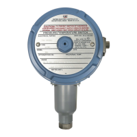
Types B100 and C100 (Immersion Stem)
Temperature variations are sensed by a liquid
filled sensor which expands or contracts against
a bellows which in turn actuates or deactuates a
snap-action switch at a predetermined set point.
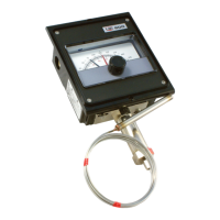
Types E100 and F100 (Bulb & Capillary)
Temperature variations of a liquid filled sensing
bulb are hydraulically transmitted to a bellows or
diaphragm which either actuates or deactuates
a snap-acting switch at a predetermined set
point.
MAXIMUM TEMPERATURE IS THE HIGH-
EST TEMPERATURE TO WHICH A SENS-
ING ELEMENT MAY BE OCCASIONALLY
OPERATED WITHOUT ADVERSELY AFFECT-
ING SET POINT CALIBRATION AND
REPEATABILITY. MAXIMUM TEMPERA-
TURE LIMITS STATED IN LITERATURE MUST
NEVER BE EXCEEDED, EVEN BY SURGES
IN THE SYSTEM. OCCASIONAL OPERATION
OF UNIT UP TO MAX. TEMPERATURE IS
ACCEPTABLE (E.G. START-UP, TESTING).
CONTINUOUS OPERATION SHOULD BE
RESTRICTED TO THE DESIGNATED
ADJUSTABLE RANGE.
Tools Needed
Adjustable wrench
Flathead screwdriver
Hammer (for alternate wire knockouts)
MOUNTING
INSTALL UNIT WHERE SHOCK, VIBRA-
TION AND TEMPERATURE FLUCTUA-
TIONS ARE MINIMAL. ORIENT UNIT SO
THAT MOISTURE IS PREVENTED FROM
ENTERING THE ENCLOSURE. SHOULD THE
CONTROL BE INSTALLED WHERE HEAVY
CONDENSATION OR WASHDOWN IS EXPECT-
ED, VERTICAL MOUNTING IS RECOMMENDED
(PRESSURE CONNECTION DOWN).
Do not mount unit in ambient temperatures
exceeding published limits. 100 Series
Temperature Controls can be mounted in any
position, provided the electrical conduit is not
facing up.
For remote mounting, mount the unit via the (2)
1/4” screw clearance holes on the enclosure
(See Dimensions on back page.) Fully immerse
the bulb and 6” capillary in the control zone.
For best control it is generally desirable to place
the bulb close to the heating or cooling source
in order to sense temperature fluctuations quick-
ly. Be sure to locate the bulb so that it will not
be exposed to temperatures beyond the instru-
ment range limits.
UNITED ELECTRIC
CONTROLS
Installation and
Maintenance Instructions
IMT100-02
Please read all instructional literature carefully and thoroughly before starting. Refer to the final page for the listing of Recommended
Practices, Liabilities and Warrantees.
100 Series
Temperature Controls
Types B100, C100, E100, F100
Part I - InstallationPart I - Installation
FOR LOCAL MOUNTING, ALWAYS
HOLD A WRENCH ON THE TEMPERA-
TURE HOUSING HEX WHEN MOUNT-
ING UNIT. DO NOT TIGHTEN BY TURNING
ENCLOSURE. THIS WILL DAMAGE SENSOR
AND WEAKEN SOLDERED OR WELDED
JOINTS.
WIRING
DISCONNECT ALL SUPPLY CIRCUITS
BEFORE WIRING UNIT. ELECTRICAL
RATINGS STATED IN LITERATURE AND
NAMEPLATES MUST NOT BE EXCEEDED-
OVERLOAD ON A SWITCH CAN CAUSE
FAILURE ON THE FIRST CYCLE. WIRE
UNITS ACCORDING TO NATIONAL AND
LOCAL ELECTRICAL CODES. MAXIMUM
RECOMMENDED WIRE SIZE IS14 AWG.
Remove the two screws retaining the cover and
cover gasket. Two cast-in 7/8” diameter knock-
outs for electrical conduit are located on the
side and rear of enclosure. These can easily be
knocked out by placing the blade of a screwdriv-
er in the groove and rapping sharply with a
hammer. A 1/2” NPT conduit connection is
located on the side of the enclosure.
Connect conduit to the case and wire directly to
the switch terminals according to local and
national electrical codes. Bring the wires up to
terminals from the rear of the case allowing
enough slack so as not to affect switch move-
ment when making setting adjustments. The
three switch terminals are clearly labeled “com-
mon”, “norm open”, and “norm closed”. If lead
wires are supplied, color coding is as follows:
A grounding screw and clamp (cast in symbol)
is provided which meets a 35 lb. pull test. Keep
the wire as short as possible to prevent interfer-
ence with the plunger and, when provided, the
adjustable differential switch wheel.
Tools Needed
5/8” open end wrench
NOTE: For set point adjustments and recalibra-
tion, connect control to a calibrated temperature
source and stabilize unit.
SPDT DPDT
(Option 1010)
SWT1 SWT2
Common Violet Violet Yellow
Normally Open Blue Blue Orange
Normally Closed Black Black Red
Part II - Adjustments Part II - Adjustments