%
e@o
INO
U
^EE
ULTRAFLEX
S,p,a,
16015 CASELLA
(GE) -
TTALY
M6.k ttrg o.partMt
!6012
AU$ILLA
(GE)
.ITALY
Tel- +39
010 - 96203m
Fäx +39 010 - 9620333
E
Iuil
ilElt
B,47 -
849
INSTALLATION INSTR
U CTIONS
WARNI
G:
THE FOLLOW|NG
INSTRUCIIONS
CONTAIN
IMPORTANT
SAF€TY INFORMATION
AND MUST
BE
FORWAROED TO THE SOAT OWNER
LEFT.SIDE IiISTALLATION
RIGHT.SIDE
INSTALLATION
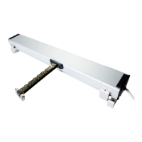
Ths control unit is d€signed lo
mouflt
on lhe
ght
or
loft
sid6 oi tho boat.
IMPORTANT SAFETY
NOT'CE:
-
Please .ead thes€ iastructions
carefu
y
bofo.e iDstallation-
-
lmprop.r us.ge or
iDcorr.ca
as-
sembly
cen result in lots of a,'-
gina
control with subt'qu.nt
danages to thinst .ad/ot iniuty
-
Th€ Manuhcturer
does not
eccePt
rßponsibiliti.s
lo.
the
inttalt.-
tions
whera non-origirrl iteas
-
lt it racommondcd
ao
petforma
ah. control tyst
m rigging with
thc bo.t flo.ting .nd tha
.ngine
847
-
849
conüol
units, using
rhe
rc-
spadivs connoclion kits, can utilize rhs
followins Ultrafl.x cables:
red)
, ths
provided
holders.
or{
KIT
(Frc.
2)
rift l€vsrs
using tir.
pivot
rs I or B' d6p.nding on
r-cäs€
ltith
tho
scr€ws Z
ß
11
(R€fsr
to
explod.rd
(]T
R23
(FtG.
3)
d on
th€ half-ca36.
P using ci.clip
)(
ßing ci?clip
0 in ono
of
c3blo
to
pivot
pin
I
tha half-crlo and
anach
.d lho bra$ washsr tl
ir,
Fig.
1
Fls.2
Fig.3
?
lli
ll",-
(o
[9.
a
a
a
a
C5
(no
connoctioo kit
r6quired)
C14
{(23
conn6clion kit rcquired)
An- CrO
(K24
connection kit requircd)
C2
-
C7 ' C8
(K25
coonedion kil rcqui
FFIcTlo
INSTALLATIO
(Fis,
1)
Fit iiiction spings 4 and friction
cäps
5 inlo ths
Pedorme this
proc6dur6
on both half-cas65.
ITiTSTALLATIO N
WITHOUT
CONNECTIO
I
for
tyPa
C5.cabl63
Anach rhe type C8 cäblss to rhrottl6 and shift
l€
Fin.
8 and
ci.clips 6 in one of lwo
posiiiofls
I
S€cur€
€ach
l6v6r
to tha corrcspoflding half-cäs(
th€
plastic
washers 10 and ü6 brass w6sh6ß
11
INSTALLATIOI{ WITH CONNECTION K]T
X
for tyE.
C'14
c.blo3
lns€n th. adaptor A
into
the holder
provid6d
on
Arbch
rh. typ6 Cl4
cabl6
to sliding block
P usi
Attach
th6
pivot pin
8 ro lho
conrol
lovor ßin[
two
politioß
6 or B'.
Connsct tha sliding block moufltod
on the c3blo
lß6n
contol
l6v$ onto hub
provid6d
in tha h
with üe screl, 7, th6
pl.rnic
wash6' 10 e.d d
(R6f6r
to sxploded visw)
Perorma
thB
proc6dur6
on both hall-ca3s6.
NOTET
Fot
this
instullaüon
th6 citclip Z is not
ul