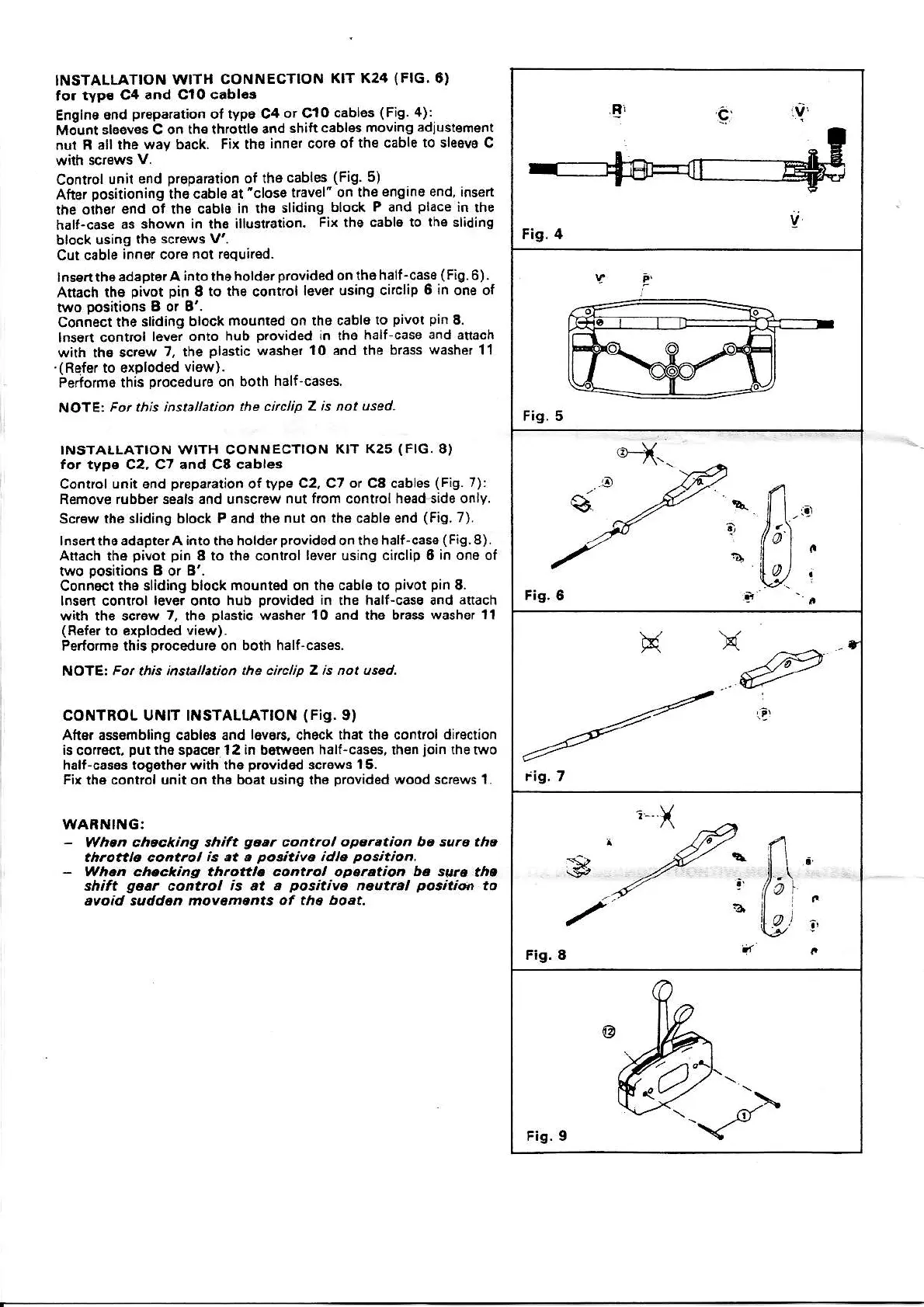
INSTALLATION
WITH CONNECTION
KIT
K24
(FIG.8)
to. typ.
C4
and CIO cabler
Enoine
end
preparation
of iype C4
or CIO cablos
{Fig.
4):
Mo,-unt sl66ves C on the lhronlo
snd
shift cablss
moving ädiuslern€nl
nut n
all lhe w.y back.
Fix tho
inner cor6 of lhe
cabl€ to sleovo
C
Conrrol
unit 6nd
prop.ralion
ol iho
cables
(Fig.
5)
After
oositioni6g
ths cäbl6 at
"close
lravel' on tha
enginB end iflsert
rhe oihor end
of
the cabl6
in lhe
sliding
block
P
and
place
in
the
hall-cas€
as shown
in
the
illustralion.
Fix lhe cäbl6
to the sliding
block
using
the screws
V'.
Cut cable
inn€l cor6
not r€quirsd-
lns€n the
adäptor A intothoholderprovided
on
tho half_case
(Fig
6).
Atach th6
pivot pin
I to the confiol
lever usiog
cnclip 6
in
ons ol
two
positions
B or B'.
Con;6ct
the 3liding
block mount€d on ths
cable
to
pivo!
pin
8.
lnson control
l6ver
onto
hub
provided
in the half-caso
and attach
with th6 screw
7, the
plastic
washer
10 and lhe brass
washer 11
.(Refer
to exoloded
vi6w).
eerforme this
orocedurs
on both
half cases
NOIE
For this instalanon
the circlip Z is not
used.
INSTALLATION
WITH CONNECTION
KTT K25
(FIG.
A)
for typs
C2,
C7 and C8 cables
Conlrol
unit end
prepaation
of type
C2, C7 or C8
cablos
(Fig.
7):
ßemove
rubber sgals and unscrew nut
frcm
control hsediide
only,
Sc.ew the sliding
block P and tho
nut
on the cabl€ end
(Fig.
7).
lnse.ttheädäpterA
into
the
holder
provided
on the half"cass
(Fig.8).
Aflach
the
pivot pin
8 to the control l6ver using circlip I
in one ol
tvvo
positions
B
or
B'.
Connoct rhe sliding block
mounted
on
rhs cabls to
pivoa pin
8.
lns6n contol
lever
onto hub
provided
in
the
half-c6se and anach
with th6 scrow
,,
tho
plastic
washer
10 and the b.a$ wäsher 11
(R€fsr
to exploded view).
Perform€ thb
procddu€
on borh
hälf-cases.
NolEt Fo. this installation the
circlip z is not used-
CONTROL UNlT ll,lSTALIATION
(Fis.
9)
Attqr ass€mbling cabl$ and
l6v6rs.
ch6ck that the conkol dkection
is
corrgct.
put
th6 spacar 1 2 in b{w6en half-cas6s, then
join
th€ two
halt-ca§8s tog6rh6. with rhe
provid6d
scr6w§
I
5-
Fir
the
control unit on th6 boat uaing th6
providod
wood
screws 1.
WAB ING:
-
Whcn checkiag thift
gt*tt
corrtrol
op.r.tion bc aura th.
thtottle conttol
is
at a
poritiyc
idl€
po§tiot
.
-
Wh.n ch.cking th.oalt. control opatation b. st ra rha
shift
ga.r
coatrol
is at e
positlva
aeutral
potitioi
to
ayoid sudd.n moveme,,ts of the boat.
Fis.5
Fis.6
X
iig.7
lt \
,
Fig.8
Fig.9
 Loading...