Doc. 81184X - Rev. 28/05/08 8-8 Dis. 15942/g
ISTRUZIONI PER LA REGOLAZIONE POSIZIONE DI CHIUSURA - INSTRUCTIONS TO ADJUST LOCKUP POSITION
INSTRUCTIONS POUR LE REGLAGE DE LA POSITION DE FERMETURE - ANLEITUNGEN ZUR EINSTELLUNG DER SCHLIESSPOSITION
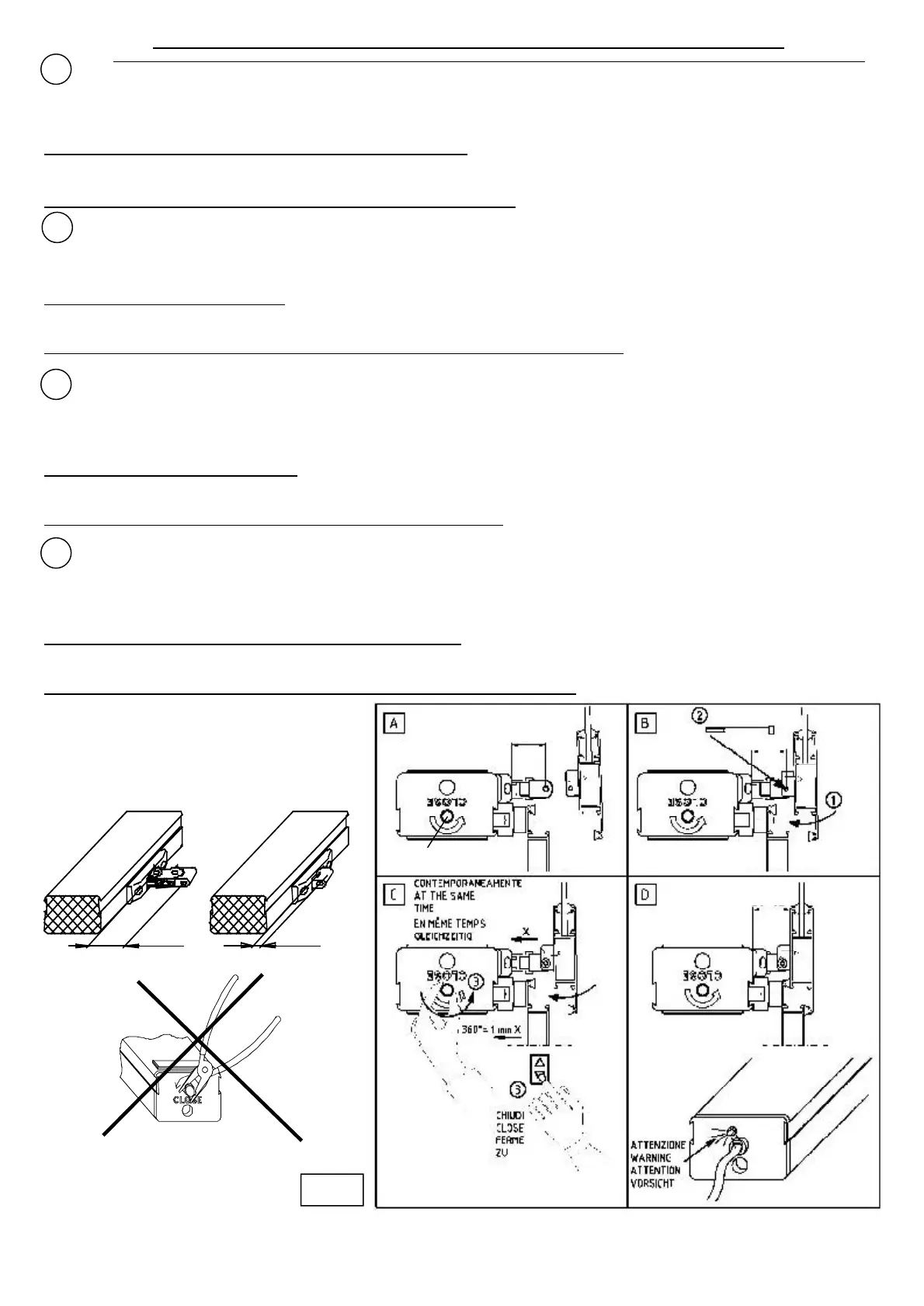
La regolazione del fine corsa in chiusura si effettua agendo contemporaneamente sulla manopola V e sul pulsante di alimentazione. Il campo di regolazione
+8$J":&()N)2"82').T)##O)FM'&&,'&(8$)J"$%$)?(8%"&()2(%)!')2'&$%')?,(8")1")B4)##)A'::$)?(8(E)8":+$&&()'!!M'&&,'&(8$X)G,"%1")'!!M$:&8$#"&L)#'--"(8$)1$!!')8$-(!'9"(%$O
%%!HSHQ%3/3%a%./55,],74% @204%65D,04% R,%.,b% 72% catena tramite la manopola V quindi, nel caso i 31 mm non siano sufficienti per c/774G205,%277)2312% -/],74c%!"!%
TENTARE DI RUOTARE la manopola V in senso orario -2%5.455/0204%102%,7%D/33411/04%def%4%,7%.0/@,7/%R477)2312H%
Comunque NON FORZARE MAI la manopola V g623R/%a%200,E212%2%@,34%D/052c%D2652%,7%R2334GG,2-431/%,31403/%R477)211621/04H%
Per fare uscire nuovamente la catena (5-31 mm) in caso di errore di regolazione:
'!"#$%&'8$)!M'&&,'&(8$)"%)'+$8&,8')?"%()')?'8$),:2"8$)!')2'&$%a di circa 50 mm, ruotare la manopola in senso orario fino al suo arresto, alimentare in chiusura: la catena torna
nelle condizioni iniziali (fuori di 31 mm.). A questo punto alimentare nuovamente in chiusura e ripetere la REGOLAZIONE.
In posizione di finestra chiusa, verificare che la spia rossa di segnalazione (led) sia accesa.
To adjust the end of stroke at the limit of travel, use simultaneously the V knob and drive the feed push-button. The adjustment range reaches approximately 26
mm. The actuator is supplied with the chain 31 mm out (hole axis) with respect to the actuator and therefore, to the furthest limit of the adjustment.
N.B.: the chain can not be pulled out any farther through the V knob, therefore, if 31 mm are not sufficient to establish a connection to the mobile
wing, DO NOT TRY TO TURN the V knob clockwise and insert a G2G4%,35142R%]41T443%1U4%D/334D1/0%def%23R%1U4%T,3G%.0/@,74H%
In any case, NEVER FORCE the V knob inward when it tightens, as it would irreversibly damage the inner mechanisms of the actuator.
Pull out the chain (5-31 mm) in case of error:
?$$1)h"&;)H(+$%K),%&"!)e5)##)(?)2;'"%)2(#$ out, turn the knob clockwise until it stops, a%1)?$$1)h"&;)H2!(:$KQ)&;$)2;'"%)":)B4)mm out.
I&)&;":):&'-$X)?$$1)'-'"%)h"&;)H2!(:$K)'%1)8$+$'&)&;$)IY•\*P}a@PO)
When the window has reached a closing position, make sure that the red visual indicator (led) is switched ON.
F$)8<-!'-$)1,)?"%)1$)2(,8:$)$%)+(:"&"(%)1$)?$8#$&,8$):M$??$2&,$)$%)'-"::'%&):"#,!&'%<ment sur la molette V et sur le bouton-pou::("8)1M'!"#$%&'&"(%O)F')+!'-$)1$)
8<-!'-$)+8<J,$)$:&)1M$%J"8(%).T)##O
FM'2&"(%%$,8)$:&)?(,8%")'J$2)!')2;'u%$):(8&"$)1$)B4)##)A'^$)1,)&8(,E)+'8)8'++(8&)L)!M'2&"(%%$,8X)1(%2X)+'8)8'++(8&)L)!M$^&8<#"&<)1$)8<-!'-$):,+<8"$,8$O)
N.B.: il est impossible de faire sortir la ch2h34%26%R47C%R4%D4114%7,-,14%C%102E405%72 molette V; si 31 mm ne suffisent pas pou0%74%02DD/0R4-431%C%72%E/741%%-/],74c%!$%
PAS TENTER DE TOURNER la molette V dans le sens des aiguilles R)634%-/3104c%-2,5%,310/R6,04%63%D/,3%43104%74%D/334D1460%def%41%le profil de la volet.
Dans tous les cas, NE JAMAIS \"+O$+%72%-/74114%:%7/05g6)4774%54%R60D,1c%D20%D472%.0/E/g6402,1%7)43R/--2G4-431%,314034%R4%7)2D1,onneur.
\2,04%5/01,0%72%DU2h34%FK-31 mm) en cas de faute:
'!"#$%&$8)$%)(,J$8&,8$)l,:G,ML)2$)G,$)!')2;'u%$):(8&$)1M$%J"8(%)e5)##X)&(,8%$8)!')#(!$&&$)1'%:)!$):$%:)1$:)'"-,"!!$:)1M,%$)#(%&8$)l,:G,ML):(%)'88p&X)+,":)'!"#$%&$8)$%)
?$8#$&,8$)Q)!')2;'u%$)$:&):(8&"$)1$)B4)##O)I)2$):&'1$X)'!"#$%&$8)L)%(,J$',)$%)(,J$8&,8$)$&)8<+<&$8)!$)jakFIkaO)
$3%./5,1,/3%R4%@43A104%@40-94c%5)2556040%g64%74%E/i231%76-,346j%0/6G4%F74RM%5/,1%2776-9H
Zur Einstellung des Anschlags beim Schlie~J(8-'%-):"%1)1"$)Y8$;>%(+?))0),%1)1$8)`$?$;!:&':&$8)-!$"2;9$"&"-)9,)=$&•&"-$%O)Y$8)J(8-$:$;$%$)j$-$!=$8$"2;)=$&8•-&)
etwa 26 mm. Bei der Lieferung ist die Kette 31 mm (Bohrungsachse) aus 1$#)I%&8"$=)',:-$?';8$%X)1':);$"~&):"$)=$?"%1$&):"2;)'#)(beren Ende des Regelbereichs.
N.B.: Die Kette kann mit Hilfe der Drehknopf V nicht weiter 265G4@2U043% T40R43H% &/77143% R,4% kl% --% 3,DU1% m6-% *35DU76n% 23% R43% \435140@7[G47
ausreichen, VERSUCHEN SIE NICHT, die Drehknopf V im Uhrzeigersinn zu%R04U43c%5/3R403%541m43%&,4%4,34%=2n5DU4,]4%mT,5DU43%R43%:4rbinder "2" und das
\7[G47.0/@,7%4,3H%X$P$!%&;$%!;$<*(&%<;#%X$o*LT VOR, sollte die Drehknopf V zu fest sitz43c%R2%45%5/351%m6%4,340%S45DUVR,G63G%R4s Antriebs kommen
^p3314H%%
Um die Kette wieder aus dem Antrieb ausgefahren (5-31 mm) falls vom fehler :
k$=$%) *"$) 1$%) €??%,%-:=$?$;!X) =":) 1"$) f$&&$) etwa 50 mm ausgefahren ist, drehen Sie den Drehknopf im Uhrzeigersinn bis zum Anschlag und geben Sie den
*2;!"$~=$?$;!Q)1"$)f$&&$)=!$"=&)B4)##)',s dem Antrieb. Denn wieder)€??%,%-:=$?$;!)-$=$%),%1)h"ederholen die EINSTELLUNG.
Y]40.0[@43%&,4%]4,%G45DU7/554340%\435140./5,1,/3c%/] die rote Kontrolleuchte (LED) eingeschaltet ist.
GB
F
D
Fig. 9
V
31
31
22-48
31 mm 5 mm
 Loading...