17 18
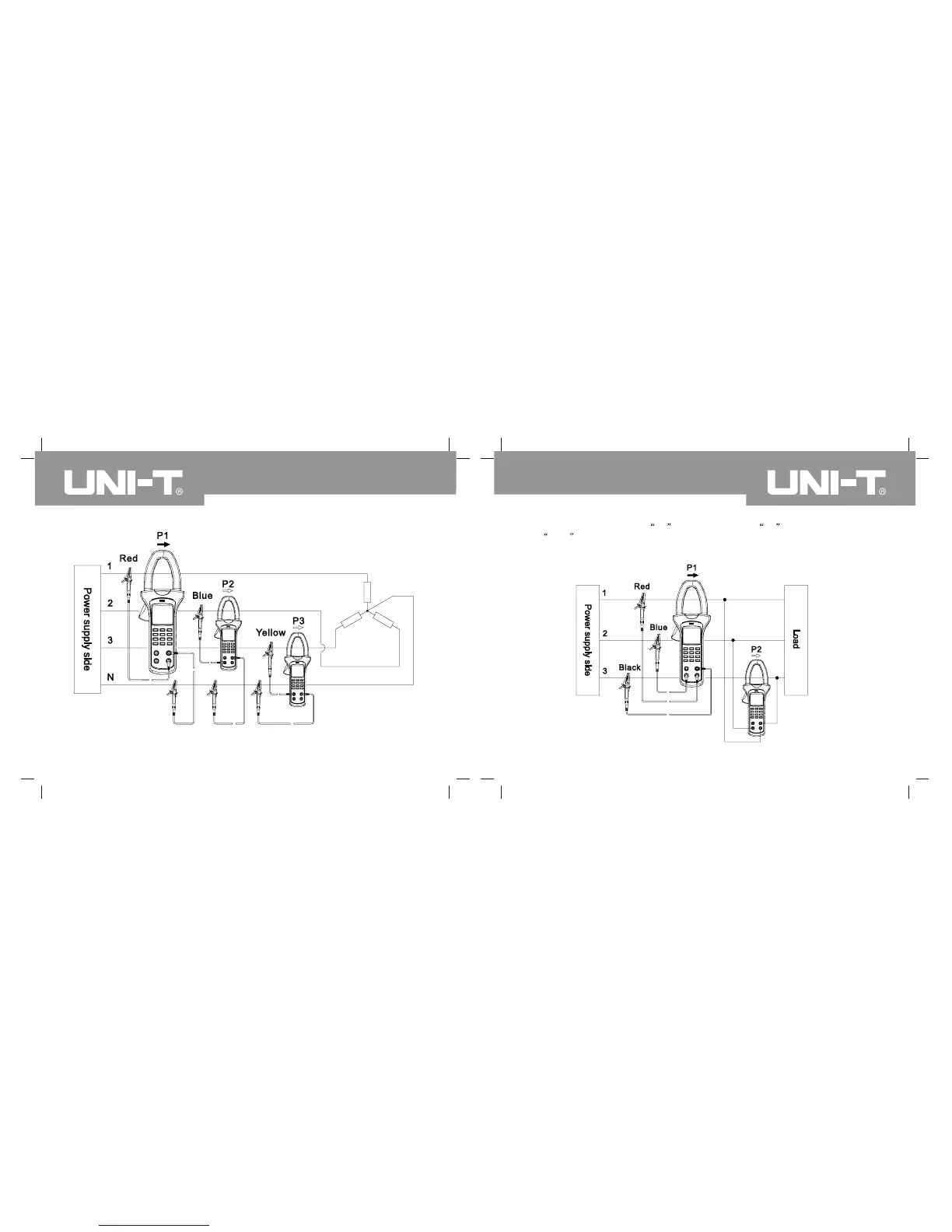
Figure 4 Power measurement of three-phase four-wire system
(As shown in Figure 5), connect V1 end/red testing pen, V2 end/blue testing pen
and COM end/black testing pen to every firing line of three-phase load respectively
during load measurement of three-phase three-wire system. V3 end/yellow testing pen also
cannot be measured.
Figure 5 Power measurement of three-phase three-wire system
UT241/242/243 OPERATING MANUALUT241/242/243 OPERATING MANUAL


 To Next Page