33 34
7.8 Phase Sequence Detection
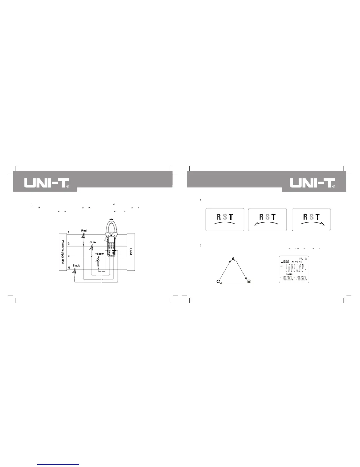
1 As shown in Figure 14, press MENU to select gear of voltage (V)+voltage (V)+voltage
(V) . Insert red testing pen into V1 jack, blue testing pen into V2 jack, yellow
testing pen into V3 jack and black testing pen into COM jack and connect 4
testing pens to measured power, three-phase load and grounding end.
Figure 14
1 As shown in Figure 15, 16 &17, instrument will display phase sequence detection result for
load loop of three-phase four-wire system.
Figure 15 Any phase of voltage
is less than 30V.
Figure 16 Inverted sequence Figure 17 Positive sequence
2 Positive sequence layout is shown in following figure. As shown in Figure 18, LCD can
display positive sequence detection result when connecting V1, V 2 and V3 jacks t o
Phase A, B & C if three-phase voltage exceeds 50V.
Positive
sequence
Figure 18
UT241/242/243 OPERATING MANUALUT241/242/243 OPERATING MANUAL


 To Next Page