Installation info
17
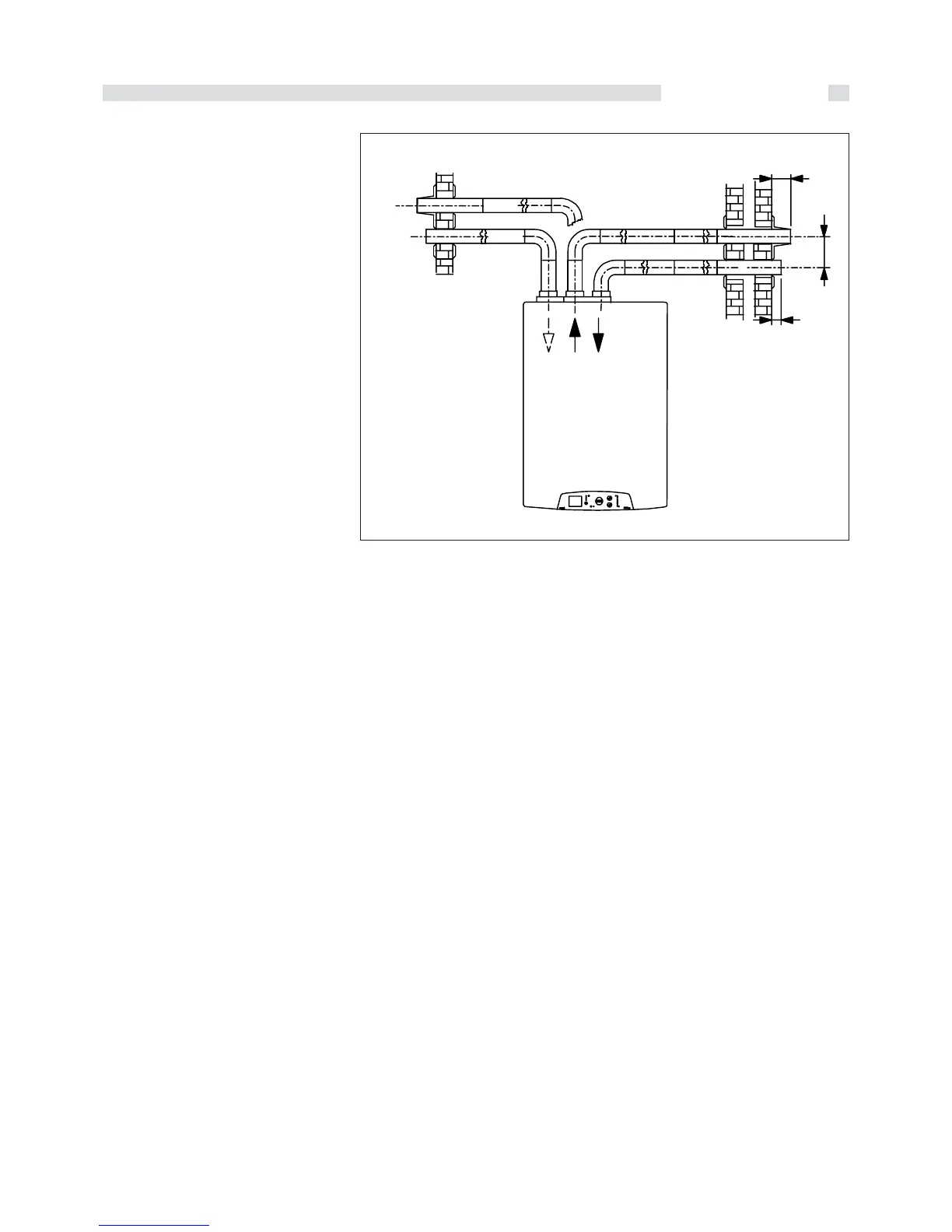
fig. 14
135
45
Hmin. = 165 mm
250 min.
Example N.2
Primary air intake from an outer wall and
smoke evacuation through the same wall.
Maximum allowed pressure drop: 72Pa
CALCULATION OF PRESSURE LOSS
FOR DISCHARGE & SUCTION
DUCTS
Bear in mind the following parameters
when calculating pressure losses:
- for each metre of duct with Ø 80 (both
suction and discharge) the pressure loss
is 2 Pa;
- for each 90° Ø 80 (R=D) bend with long
radius, the pressure loss is 4 Pa;
- for the Ø 80 L = 0.5 m horizontal air inlet
terminal, the pressure loss is 3 Pa;
- Ø 80 L = 0.6 m horizontal discharge end
section, the pressure loss is 5 Pa;
NB: These values refer to discharges
through original UNICAL non-
flexible and smooth ducts.
In both of the following examples
the hypotized compositions of the
intake and evacuation ducts are
possible because the total pressure
loss is lower than 72 Pa, which is
the maximum allowed pressure loss.
Example of check using wide radius
bends:
- 15 m duct Ø 80 x 2 = 30 Pa
- 2x90° Ø80 long radius bends 2x4= 8 Pa
- horizontal Ø 80 air inlet terminal = 3 Pa
- horizontal Ø 80 terminal = 5 Pa
Total pressure loss = 46 Pa
Example N.2