Installation info
20
fig. 20
A6
65432 17
7654321
A2
BLUE
BROWN
SS
E. RIV.
TEFLON WHITE
ROD
A9
BROWN
V
BLUE
YEL/GREEN
32 1
SR
GREEN
BROWN
WHITE
BLUE
87 65432 1
A3
4321
A1
54 321
A4
WHITE
WHITE
WHITE
WHITE
WHITE
BLUE
BLUE
BLUE
BROWN
GREEN
VERSIONE
TN
VERSIONE
TFS
5 432 1
DK
TF
TL
PV TL
MD
A8
65 43 2 1
BROWN
BLUE
YEL/GREEN
BROWN
BLUE
YEL/GREEN
PS
PR
BROWN
E. ACC. 1
TEFLON RED
TEFLON RED
V2V1
E. ACC. 2
BLUE
BROWN
BLUE
YEL/GREEN
DISPLAY PCB
BROWN
SE
TA 1
BLACK
BLUE
YEL/GREEN
L1
N
L1
N
ALIMENTATION
230 V - 50 Hz
IG
54321
GND1
GND2
GND4
ROD
N
Y2
GND5
L1 EXT
SENSOR
Y1
A8
7654321
43217654
8
321
2 1
21
A6
A9
A3 A1 A2 A4
TA 2
EVZ
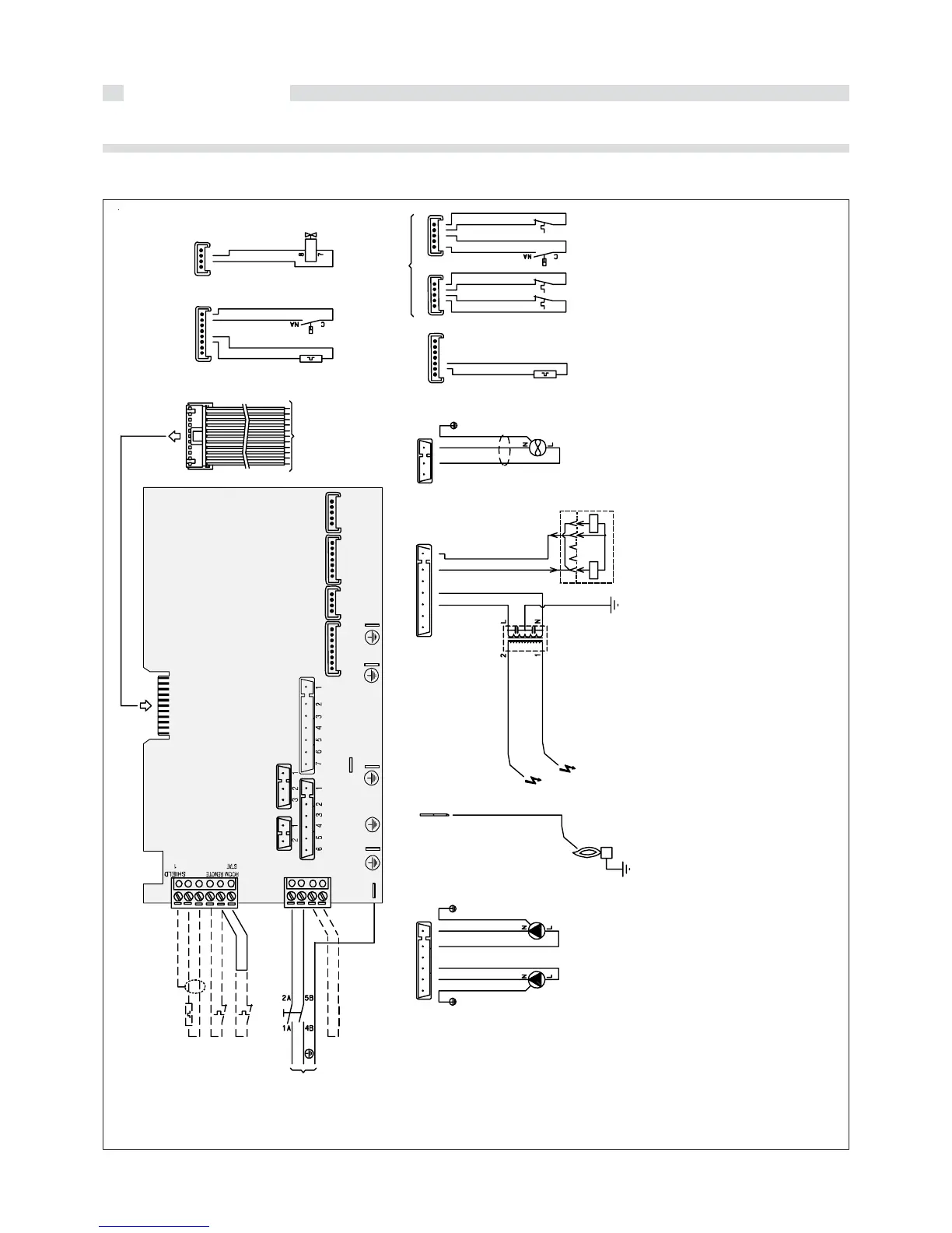
2.3 - ELECTRICAL WIRING
2.3.1 - ACTUAL CONNECTION DIAGRAM
KEY
A1…A8 = Utility connectors
ROD = Ionization electrode connection
on the main board
Y1 = Room thermostat and outer
sensor connectors
Y2 = Voltage connector
DK = Pressure switch for low water
level
E. RIV. = Ionization electrode
E.ACC1 = Ignition electrode
E.ACC2 = Ignition electrode
MD = Modulating coil
PR = Heating pump
PS = Sanitary pump
PV = Fan pressure switch (only fan
assisted version)
SE = Outer sensor (optional)
SS = D.H.W. temperature sensor
SR = C.H. temperature sensor
TA = Room thermostat (optional)
TF = Flue gas antispillage thermostat
(natural draught version)
TL = Limit thermostat
V = Fan (only fan assisted version)
VG = Gas valve
JP1 = Jumper for on/off or modulating
chronothermostat selection (see
page 22)
JP2 = Jumper for boiler version
selection (natural draught or fan
assisted)