Installation info
18
fig. 17
1
2
fig. 15
1
2
TSC0210C
ADA0160C
Analyser
probes
Analyser
probes
Smokes
Air
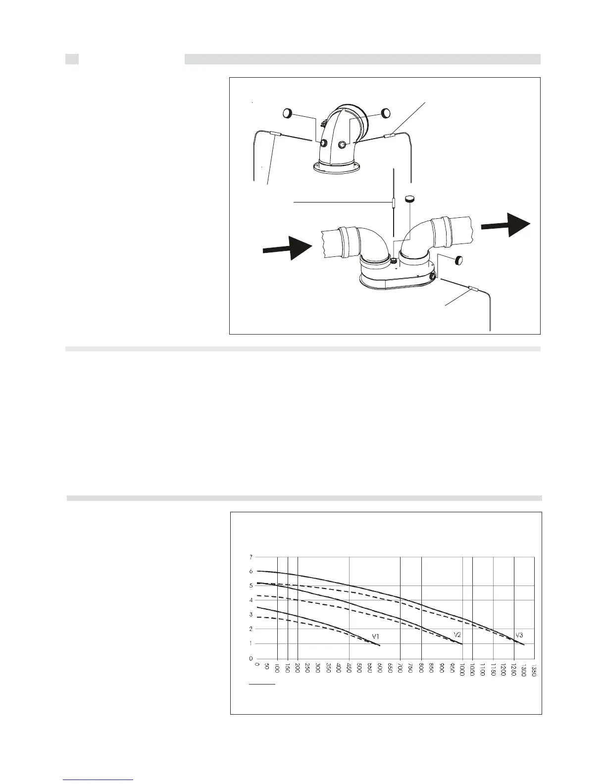
2.2.9 - ON SITE COMBUSTION
EFFICIENCY MEASUREMENT
Coaxial ducts
(Type A accessories)
To determine combustion efficiency the
following measurements must be made:
- the combustion air temperature measured
in hole 2 (see fig. 15).
- the flue gas temperature and CO2 %
measured in hole 1 (see fig. 15).
Make these measurements with the
boiler running in a steady state
condition.
(Type B accessories)
Separate ducts
To determine combustion efficiency the
following measurements must be made:
- the combustion air temperature measured
in hole 2 (see fig. 15).
- the flue gas temperature and CO2 %
measured in hole 1 (see fig. 15).
Make these measurements with the
boiler running in a steady state
condition.
Analyser
probes
2.2.10 - GAS SUPPLY LINE
The gas supply line must have a diameter
equal or larger than the one used in the boiler.
Comply with the applicable local installation
requirements which shall be considered as
having been incorporated in full in this
manual.
Before opening the internal gas supply
system; i.e. before connecting the gas
meter, all seals must be checked.
If any part of the system is concealed the
seals must be checked before the pipes
are covered.
The seal test must be conducted using air
or nitrogen at a pressure of at least 100
mbar.
The commissioning of the boiler also
includes the following operations and
checks:
- Opening of the gas gate valve and venting
of the air contained in the piping and boiler,
proceding appliance by appliance.
- Check, with the gate valve of all the
appliance
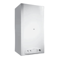
DIAGRAM FLOW RATE/MANOMETRIC HEAD AVAILABLE FOR C.H. SYSTEM
= By-Pass CLOSED
= By-Pass OPEN
..............
Flow rate l/h (Q)
Available Manometric Head m c.e.
2.2.11 - HYDRAULIC CONNECTIONS
Before installing the boiler we recommend
that the system be cleaned to remove any
impurities which could originate from
components and which could risk damaging
the circulating pump and heat exchanger.
HEATING
The heating flow and return must be
connected to the relevant ¾” connections
of the boiler M and R (see fig. 5).
When determining the size of the heating
circuit pipes it is essential to bear in mind
the pressure losses induced by radiators,
any thermostatic valves, radiator cut-off
valves and the configuration of the system.
In the boiler, between the flow and return
pipes,an automatic bypass device is fitted
(a differential valve with a flow rate of
about 150 l/h) which guarantees always
minimum flow rate through the heat
exchanger, also in the case, for instance,
that all the thermostatic valves fitted on the
radiators, are closed.
Off, that there are no gas leaks.
During the 2nd quarter of a hour from the
beginning of the test no pressure reduction
is to be detected on the gas pressure
gauge. If gas leaks have to be found, use
only water soap solution or any other
specific gas leak detector which can be
available on the market. Never look for gas
leaks using a nacked flame.