23
Installation info
A
B
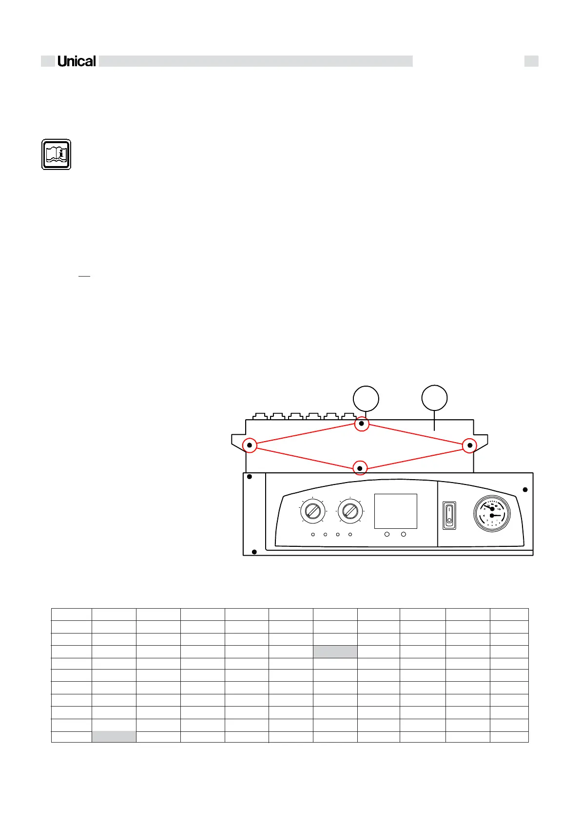
2.2.15 - ELECTICAL CONNECTIONS
The electrical connections of Logamax are
shown in the clause ‘’WIRING DIAGRAMS’’
(par. 2.3 - pag. 24)
The boiler must be connected to
the mains supply at
230 V - 50 Hz. This connection is
to be perfectly done, as foreseen
by the IEC and local rules and must be ear-
thed.
This fundamental requirement for safety pur-
poses must be checked; in case of doubt,
ask for a professionally qualified technician
to check the electrical system.
UNICAL disclaims all liability for damage or
injury caused by failure to earth the system
properly.
Gas, domestic water and central heating
pipes are not suitable for earthing purpo-
ses.
The boiler is supplied with 1.5 m long
3x0,75mm² cord.
A double pole switch with a distance between
the contacts higher than 3 mm, must be in-
stalled upstream the boiler to enable all main-
tenance operations to be carried out safely.
Access to the electrical terminal strip
- WARNING! Switch off the electrical sup-
ply
- Remove the casing.
- Remove the four screws (A) and the cover
(B) in order to get access to the connec-
tions area.
Replacement of the feeding cord
Should the feeding cord be replaced, you have
to use the original cable code 00610308.
- Approach the feeding connector Y2.
- Introduce the feeding cord through the ex-
tractable cable clamp.
- Extract the connector Y2 and proceed with
the connections according to the positions
and to the colours. The female faston of
the earth wire must be introduced in the
male faston GND1.
Connection of the ON/OFF room thermo-
stat (RT)
- Approach the connector Y1.
- Remove the existing jumper and connect,
on its place the room thermostat cable,
passing it through one of the cable clam-
ps avaible.
Connection of the room modulating ther-
mostat (OT)
- Approach the connector Y1.
- Connect the room thermostat cable, pas-
sing it through one of the cable clamps
avaible.
- The modulating chronothermostat is to be
connected exactly to the same terminal of
the ON/OFF room thermostat; in this case
the jumper JP2 has to be changed of posi-
tion (see. par 2.3.2).
For a multi-zones temperature control it is not
possible to install the modulating chronother-
most.
Example: At 25°C, the nominal resistance is 10067 Ohm
At 90°C, the nominal resistance is 920 Ohm
Relation between the temperature (°C) and nominal resistance (Ohm)
of the heating sensor SR and D.H.W. sensor SS
TABLE OF RESISTANCE VALUES AS A FUNCTION OF THE TEMPERATURE
OF THE HEATING SENSOR (SR) AND D.H.W. SENSOR (SS)
T°C0123456789
0 32755 31137 29607 28161 26795 25502 24278 23121 22025 20987
10 20003 19072 18189 17351 16557 15803 15088 14410 13765 13153
20 12571 12019 11493 10994 10519 10067 9636 9227 8837 8466
30 8112 7775 7454 7147 6855 6577 6311 6057 5815 5584
40 5363 5152 4951 4758 4574 4398 4230 4069 3915 3768
50 3627 3491 3362 3238 3119 3006 2897 2792 2692 2596
60 2504 2415 2330 2249 2171 2096 2023 1954 1888 1824
70 1762 1703 1646 1592 1539 1488 1440 1393 1348 1304
80 1263 1222 1183 1146 1110 1075 1042 1010 979 949
90 920 892 865 839 814 790 766 744 722 701