28
Adjustment info
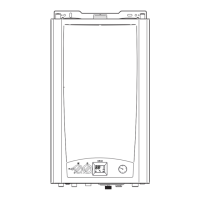
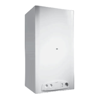
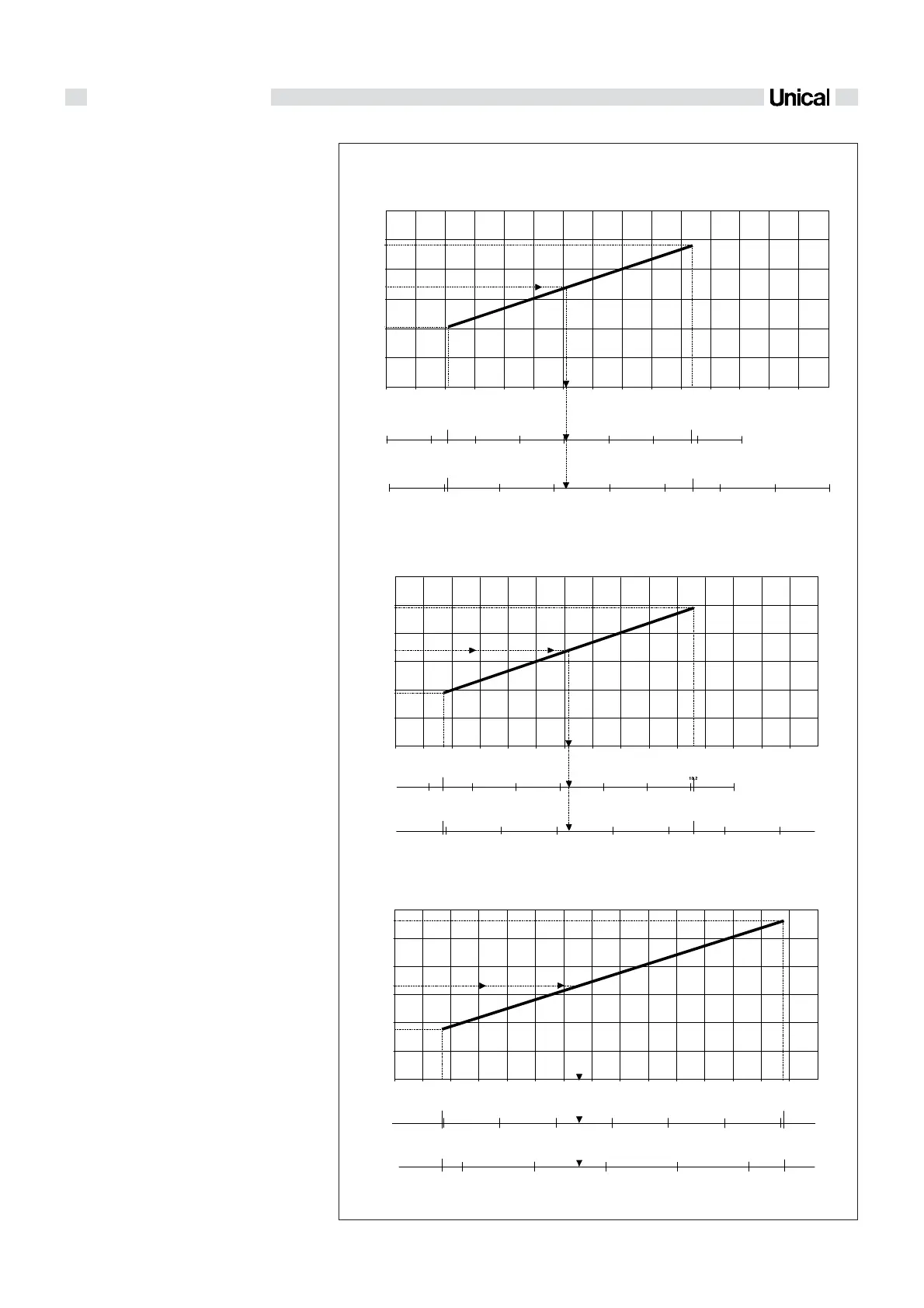
fig. 34
IVEN 04 CTN 24 F - IVEN 04 RTN 24 (A)
IVEN 04 CTFS 24 F - IVEN 04 RTFS 24 (B)
IVEN 04 CTFS 28 F - IVEN 04 RTFS 28 (C)
5
10
0123456789
11
12 13 14 15
0
10
15
20
25
30
24 , 03
10,0 1
2,1
10,4
0
5 10152025303540
5,3
27,6
5
10
15 20 25 30
0
35 40
6,9
34,2
Output kW
Natural gas G20 - 20 mbar
Butan 28-30 mbar
Propan 37 mbar
5
10
Output kW
0123456789
11
12 13 14 15
0
10
15
20
25
30
28
9,8
1,7
0
5
10 15
20 25
3,6
27,5
510
15 20
25
30 35
0
13,8
Natural gas G20 - 20 mbar
Butan 28-30 mbar
Propan 36 mbar
5
10
0123456789
11
12 13 14 15
0
10
15
20
25
30
24,5
9,95
1,7 10 ,6
0 5 10 15 20 25 30 35
4,8
27,3
5
10
15
20 25 3 0 35
40
0
Natural G20 - 20 mbar
Butan 28-30 mbar
Propan 36 mbar
Output kW
2.8 ADJUSTEMENT OF
THE OUTPUT TO
THE C.H. SYSTEM'S
NEEDS
Connect the pressure gauge to the burner as
previously shown in fig. 30, switch on the boi-
ler in heating mode and proceed as follows:
- Wait about 50 sec. to allow the burner pres-
sure to reach the standard operating va-
lue.
- Check the pressure value and through the
diagrams of fig. 34 estimate if the boiler
output is correct for heating needs.
- If not, act on the adjuster ''1 CH-POWER''
(fig. 31) on the panel board and turn it to
reach the desired value (clockwise to in-
crease, or anticlockwise to reduce the
pressure).
- Then establish the pressure value corre-
sponding to the required output.
Example:
Assuming that the heating system which is
using a IVEN CTN 24 F boiler has a total ab-
sorption of 17 kW. Using the graph ‘’A’’ in fi-
gure 34 it is possible to determine the burner
pressure, which will be:
- 6,18 mbar if the boiler runs on natural gas
- 20,5 mbar if the boiler runs on propan gas.
- 16,3 mbar if the boiler runs on butan gas.
Acting on potentiometer 1 - CH POWER set
the pressure resulting from the diagram.
GAS PRESSURE BURNER DIAGRAM CORRESPONDING TO
THE SYSTEMS OUTPUT