UM621 Series Hardware Reference Design
1
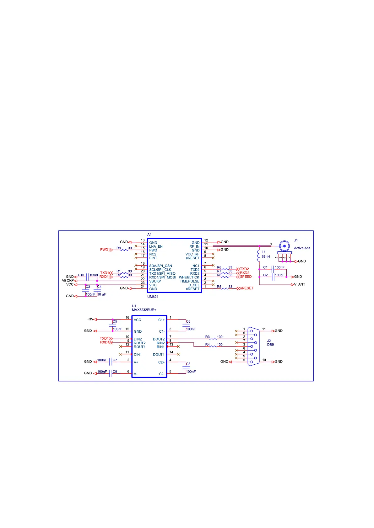
1 Reference Circuit Using an Active Antenna
The supply voltage for VCC is 2.7 V ~ 3.6 V
Ground all GND pins of the module
Connect the RF_IN signal to the antenna; note the 50 Ω impedance matching
Feed the antenna with external power supply
If the antenna power supply and the module’s main supply VCC use the same
power rail, the ESD, surge and overvoltage from the antenna will have an effect
on VCC, which may cause damage to the module. Therefore, it’s recommended
to design an independent power rail for the antenna to reduce the possibility of
damage to the module.
The supply voltage for VBCKP is 1.7 V ~ 3.6 V
Requirement for the odometer speed pulse: width ≥ 100 μs, frequency ≤ 5K Hz
 Loading...