Do you have a question about the unicore UM982 and is the answer not in the manual?
Lists the key physical and functional attributes of the UM982 module.
Details technical specifications including channels, constellations, frequencies, and power.
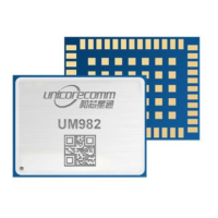
Specifies the package type of the module.
Provides the physical size of the module.
States the weight of the module.
Defines the normal operating temperature range.
Defines the acceptable range for storage temperature.
Specifies the humidity limits for operation.
Details the vibration resistance standards.
Details the shock resistance standards.
Lists the available UART ports.
Indicates the status of the I2C interface.
Indicates the status of the SPI interface.
Indicates the status of the CAN interface.
Describes the function of the RF signal processing chain.
Details the core GNSS SoC and its capabilities.
Lists the external communication interfaces available on the module.
Defines the ground pins essential for module operation.
Specifies the input for the GNSS master antenna.
Backup power pin for RTC and registers.
Specifies the absolute maximum voltage for the power supply.
Specifies the absolute maximum input voltage for pins.
Defines the maximum signal voltage for antenna inputs.
Specifies the maximum RF input power for antennas.
Defines the absolute maximum storage temperature.
Specifies the operating range for the power supply voltage.
Defines the maximum allowable ripple on the VCC supply.
Specifies the typical working current consumption.
Defines the normal operating temperature range.
States the typical power consumption in mW.
Defines the thresholds for input voltage levels.
Defines the voltage levels for output signals.
Specifies the optimum input gain for the antenna.
Specifies the overall length, width, and height of the module.
Details key dimensions relevant for PCB mounting and placement.
Provides a basic circuit schematic and component recommendations.
Recommends specific RF inductor values for L1 and L2.
Recommends capacitor values for decoupling and DC blocking.
Recommends a specific pull-up resistor value for R1.
Notes on feed inductor and decoupling/blocking capacitor selection.
Guides selection of ESD and TVS diodes for antenna feed protection.
Details requirements for VCC power-on and power-off characteristics.
Details requirements for V_BCKP power-on and power-off characteristics.
Explains the role of pads for grounding and thermal management.
Provides important notes on PCB pad design for testing and RF integrity.
Details the design considerations for RF pin pads to minimize interference.
Specifies parameters for the temperature rising phase during soldering.
Specifies parameters for the preheating phase during soldering.
Specifies parameters for the reflux phase during soldering.
Specifies parameters for the cooling phase during soldering.
Details the information present on the product label.
Describes the standard packaging method using carrier tape and reel.
Details packaging in vacuum-sealed bags with desiccant for moisture protection.
Emphasizes adherence to IPC standards for module handling.
| Brand | unicore |
|---|---|
| Model | UM982 |
| Category | Control Unit |
| Language | English |