UM982 User Manual
14 Hardware Design UC-00-M31 EN R1.2
3.2 Antenna Feed Design
When feeding the antenna from the outside, you can use devices with high power and
that can withstand high voltage. Gas discharge tube, varistor, TVS tube and other high-
power protective devices may also be used in the power supply circuit to improve the
protection.
If the antenna feed supply ANT_BIAS and the module’s main supply VCC use the same
power rail, the ESD, surge and overvoltage from the antenna will have an effect on VCC,
which may cause damage to the module. Therefore, it is recommended to design an
independent power rail for the ANT_BIAS to reduce the possibility of module damage.
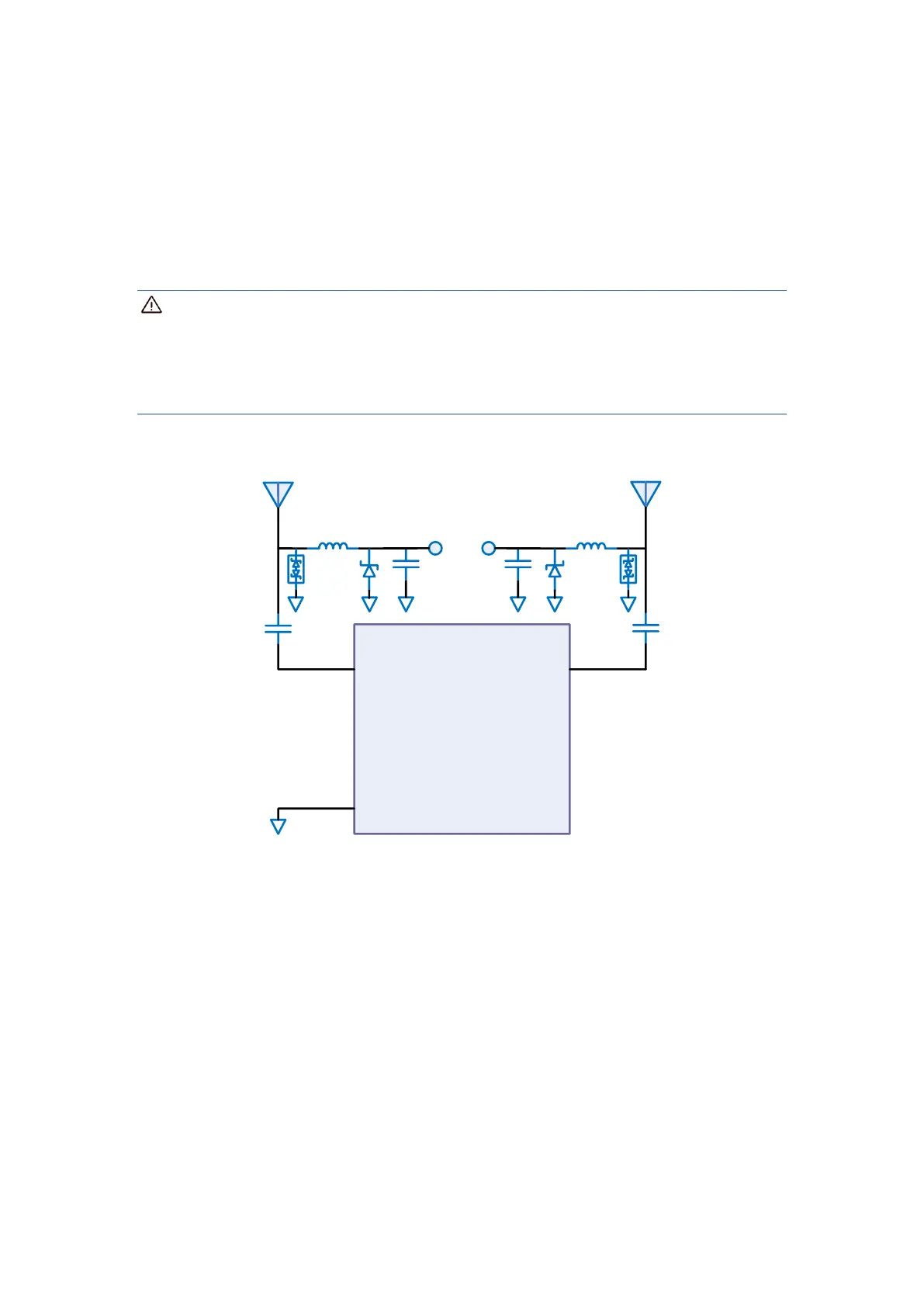
Figure 3-2 UM982 External Antenna Feed Reference Circuit
Notes:
L1 and L2: feed inductor, 68 nH RF inductor in 0603 package is recommended
C1and C3: decoupling capacitor, recommended to connect two capacitors of 100 nF /
100 pF in parallel
C2 and C4: DC blocking capacitor, recommended 100 pF capacitor
D1and D4: ESD diode, choose the ESD protection device that supports high frequency
signals (above 2000 MHz)
D2 and D3: TVS diode, choose the TVS diode with appropriate clamping specification
according to the requirement of feed voltage and antenna withstand voltage