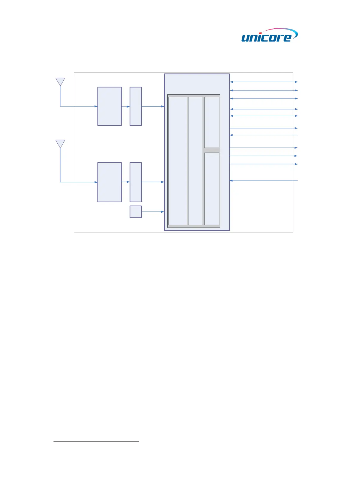
Figure 1-2 UM982 Block Diagram
RF Part
The receiver gets filtered and enhanced GNSS signal from the antenna via a coaxial
cable. The RF part converts the RF input signals into the IF signals, and converts IF
analog signals into digital signals required for NebulasIV
TM
chip (UC9810).
NebulasIV
TM
SoC (UC9810)
NebulasIV (UC9810) is UNICORECOMM’s new generation high precision GNSS SoC with
22 nm low power design, supporting all constellations, multiple frequencies, and 1408
super channels. It integrates a dual-core CPU, a high speed floating point processor and
an RTK co-processor, which can fulfill the high precision baseband processing and RTK
positioning/heading independently.
External Interfaces
The external interfaces of UM982 include UART, I
2
C
*
, SPI
*
, CAN
*
, PPS, EVENT, RTK_STAT,
PVT_STAT, ERR_STAT, RESET_N, etc.
*
I
2
C, SPI, CAN: reserved interfaces, not supported currently