EasyManua.ls Logo

Unigas C120A - User Manual

Unigas C120A
116 pages
Print Icon
To Next Page IconTo Next Page
Loading...
M039441CB Rel 0.0 10/2021
BURNERS - BRUCIATORI - BRULERS - BRENNER - QUEMADORES -
ГОРЕЛКИ
MANUAL OF INSTALLATION - USE - MAINTENANCE
C85A
C120A
Microprocessor controlled
LMV5x
Gas burners

Other manuals for Unigas C120A

Question and Answer IconNeed help?

Do you have a question about the Unigas C120A and is the answer not in the manual?

Summary

DANGERS, WARNINGS AND NOTES OF CAUTION

GENERAL INTRODUCTION

Provides essential safety information for users and installers, emphasizing qualified personnel and product compliance.

SPECIAL INSTRUCTIONS FOR BURNERS

Details specific safety instructions and warnings related to the installation and operation of burners.

ELECTRICAL CONNECTION

Covers essential safety regulations and requirements for the electrical connection of the unit.

FIRING WITH GAS, LIGHT OIL OR OTHER FUELS

GENERAL

General instructions for installation and commissioning of burners with various fuel types.

SPECIAL INSTRUCTIONS FOR USING GAS

Specific instructions and precautions for the safe operation of gas burners.

BURNER SAFETY

PART I: SPECIFICATIONS

BURNERS FEATURES

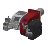
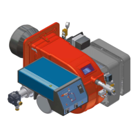
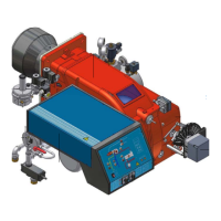
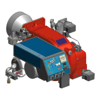
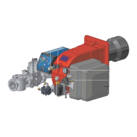
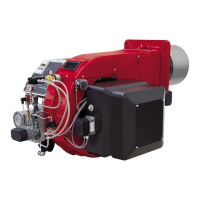
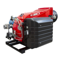
Describes the main features and components of the burners, including gas operation details.

Technical Specifications

How to read the burner “Performance curve”

Checking the proper gas train size

PART II: INSTALLATION

MOUNTING AND CONNECTING THE BURNER

Provides instructions for transport, storage, packing, and handling of the burner during installation.

Fitting the burner to the boiler

GAS TRAIN CONNECTIONS

Procedure to install the double gas valve unit

Step-by-step guide for installing the double gas valve unit and mounting the gas train.

MultiBloc MB-DLE - Assembling the gas train

Mounting VD-R & PS-...

Siemens VGD20.. e VGD40..

Details regarding Siemens VGD20.. and VGD40.. gas valves with pressure governor.

PART III: OPERATION

LIMITATIONS OF USE

Defines the intended use of the burner and conditions for improper or dangerous operation.

ADJUSTING AIR AND GAS FLOW RATES

Start-up procedure

Main menu

Fault History

Setting the temperature;pressure set-point value

Cold start thermal shock (CSTP)

Adjusting the combustion head

Calibration air and gas pressure switches

PART IV: MAINTENANCE

ROUTINE MAINTENANCE

Lists the recommended annual or bi-annual maintenance operations for the burner.

Gas filter maintenance

Replacing the electrodes

WIRING DIAGRAMS

TROUBLESHOOTNG GUIDE Gas operation

1 WIRING RECOMMENDATIONS

1.1 Earthing

Details earthing systems (TN-S, TN-C-S) and protective/functional earth connections.

1.4 Wireway and electrical conduit

2 AZL display;programming unit

2.1 LMV5 x program operating phases

4 Actuators

4.1 Addressing the actuators

Explains the process of assigning functions to actuators via addressing.

5 Setting the load controller

6 Setting the probes and set-points

6.1 Configuration of a temperature probe at X60 door

Procedure to configure a temperature probe connected to the X60 terminal.

6.4 Setting the setpoint and the burner and the PID operative band.

6.4.1 Set-point

Instructions for setting the temperature set-point value for the generator.

7 VSD Standardization

9 ADJUSTING THE AIR;FUEL RATIO CURVES

9.1 Fuel burner settings - curve-points

Details on setting fuel burner curve points for low flame stage.

10 Configurations for burner with FGR

10.2 Address and activate the AUX3 servomotor.

Guide to addressing and activating the AUX3 servomotor for FGR functionality.

10.5 FGR mode choice

11 Cold start thermal shock (CSTP)

12 BURNER MANUAL OPERATION

Unigas C120A Specifications

General IconGeneral
BrandUnigas
ModelC120A
CategoryBurner
LanguageEnglish

Related product manuals