PARTE I: MANUAL DE INSTALACIÓN
9
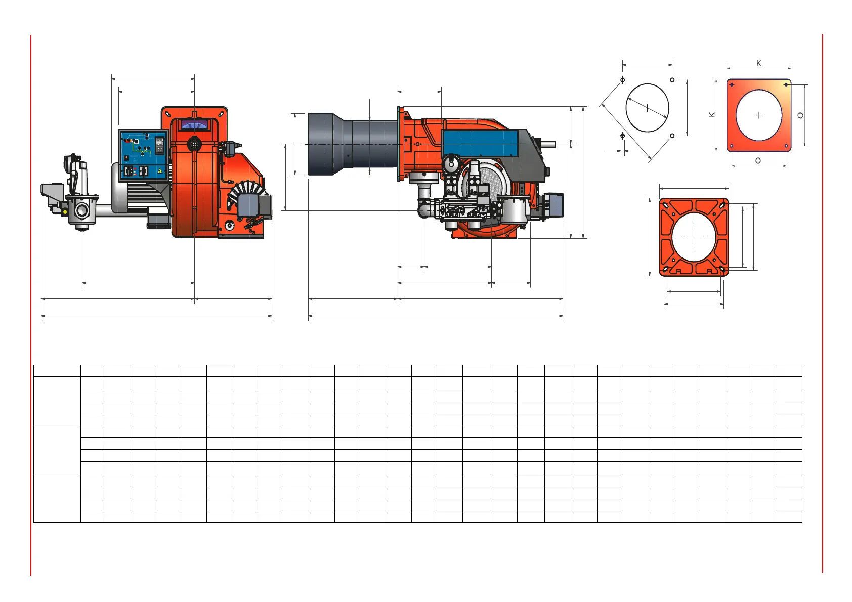
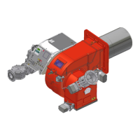
DIMENSIONES (mm) - P91A, P92A, P93A, P512A-P515A, P520A, P525A
,** Montar una contrabrida entre quemador y caldera. La alternativa es hacer el agujero H más pequeño, pero superior a la medida Y y montar la tobera al intereior de la caldera.
NOTA: las dimensiones de estorbo son referidas a quemadores abastecidos de válvulas Siemens mod. VGD.
BS = tobera estándar BL = tobera larga DN = Diámetro de las válvulas gas
B*: Las longitudes especiales de las boquillas se acordarán con la Cib Unigas
DN* A AA B BB C CC D E F G H J K L M N Omin Omax P Q R S U V W Y Z
P91A
50 1408 242 490 419 918 422 1283 852 431 265 295 329 360 466 M12 417 280 310 295 522 148 374 624 216 651 228 185
65 1408 242 490 419 918 422 1388 957 431 265 295 288 360 466 M12 417 280 310 295 551 148 403 750 313 651 228 185
80 1408 242 490 419 918 422 1390 959 431 265 295 307 360 466 M12 417 280 310 295 592 148 444 750 324 651 228 185
100 1408 242 490 419 918 422 1480 1049 431 265 295 447 360 592 M12 417 280 310 295 672 148 524 824 405 777 228 185
P92A
50 1408 242 490 419 918 422 1283 852 431 269 299 329 360 466 M12 417 280 310 295 522 148 374 624 216 651 228 185
65 1408 242 490 419 918 422 1388 957 431 269 299 288 360 466 M12 417 280 310 295 551 148 403 750 313 651 228 185
80 1408 242 490 419 918 422 1390 959 431 269 299 307 360 466 M12 417 280 310 295 592 148 444 750 324 651 228 185
100 1408 242 490 419 918 422 1480 1049 431 269 299 447 360 592 M12 417 280 310 295 672 148 524 824 405 777 228 185
P93A
50 1413 242 495 460 918 422 1283 852 431 304 344 329 360 466 M12 417 280 310 295 522 148 374 624 216 651 228 185
65 1413 242 495 460 918 422 1388 957 431 304 344 288 360 466 M12 417 280 310 295 551 148 403 750 313 651 228 185
80 1413 242 495 460 918 422 1390 959 431 304 344 307 360 466 M12 417 280 310 295 592 148 444 750 324 651 228 185
100 1413 242 495 460 918 422 1480 1049 431 304 344 447 360 592 M12 417 280 310 295 672 148 524 824 405 777 228 185
E
U
F
D
G
A
B
Q
V
J
C
L
Z
K
K
O min.
O max.
O
m
a
x
.
O
m
in
.
Plantilla de perforación reco-
mendada de la placa de la cal-
Brida quemador
P9xA
P5xxA


 To Next Page