6
Headroom, ensitivity and VPL/Gain settings.
NOTE
NOTE
The input amplifier and limiter system I designed to accommodate extreme of
performance. Typically, exceeding maximum input by much as +10dB will only result in a
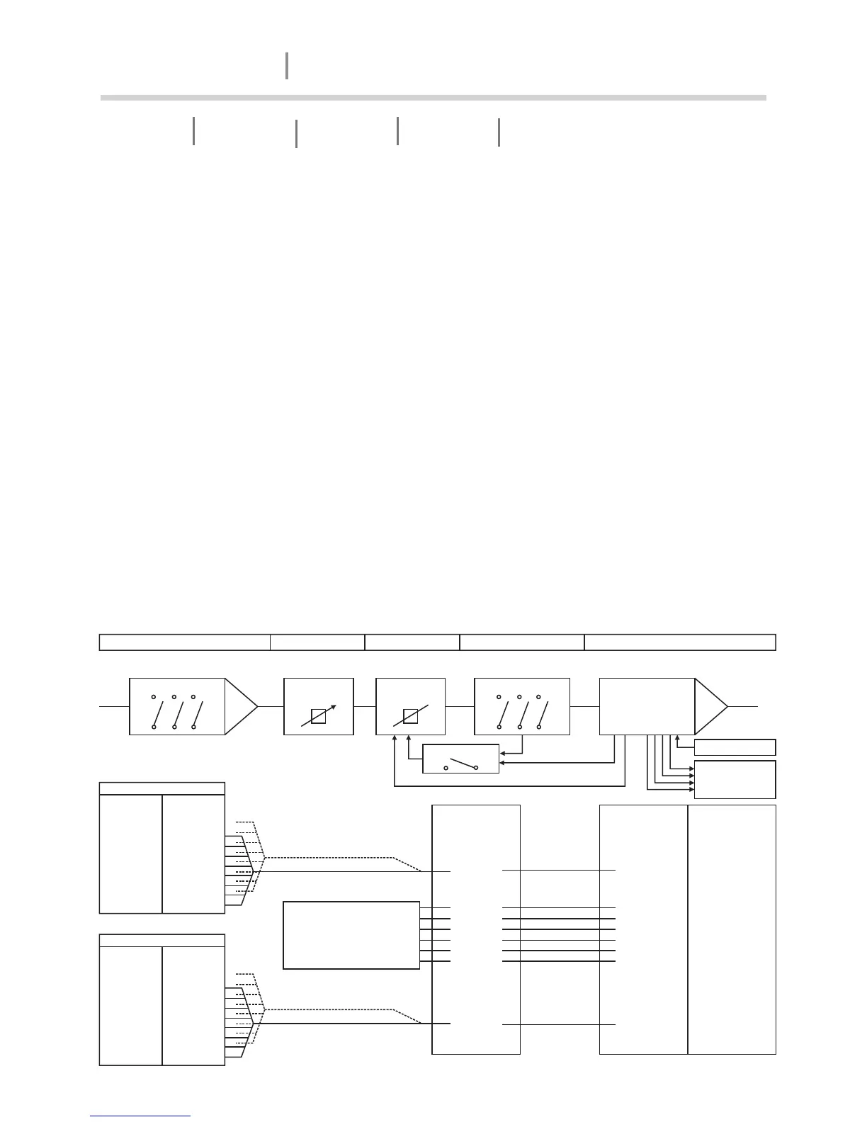
1% increase in distortion. The following schematics illustrate how the adjustable VPL and
Gain circuitry affect input sensitivity and output power.
The tables to the left of the figure 4 in page5 show input sensitivity foraTD14000with a 2
ohm load and 195Vpeak(max.) and 54 V peak(Min.) respectively for the eight different gain
stages between +23 dB and +44 dB. The resulting output power is displayed in dBu, Vrms
and watts in the tables to the far right.
The headroom available through the input stage to the clip limiter is shown by the dotted
lines as +10 dB at 195 V peak and +16.1 dB at54 V peak. These lines illustrate the
additional signal level that can be accepted at the input before any significant distortion will
appear at the input stage.
If you use the level potentiometer in the signal chain to reduce the level by an
amount greater than the headroom relative to input sensitivity AND you drive
the amplifier to clip level, you in danger of clipping the input stage before the
current or voltage peak limiter are activated.
When bridging two channels, you must add +6 dB to the input sensitivity to
achieve maximum output voltage due to the automatic -6 dB gain compensation
inserted by the amplifier.
Gain select switches Front panel
potentiometer
Dynamic Gain
reduction
VPL select switches
Class TD
Hard/Soft switch
Voltage Clip sensing
Current clip sensing
Control Mute
Monitoring Level
Temperature
Fault/Warning
Input Amplifier Level control Clip Limiter Voltage Peak Limiter Output Power Amplifier
VPL set to 195 VPEAK
Input
sensitivity
dBu / Vrms
1,0 / 0,87
4,1 / 1,23
7,0 / 1,7
10,0 / 2,5
13,0 / 3,5
16,0 /4,9
19,0 /6,9
22,0 / 9,8
Gain set to:
(DIP-switches)
+44 dB
+41 dB
+38 dB
+35 dB
+32 dB
+29 dB
+26 dB
+23 dB
+10 dB headroom to clip
relative to input sensitivity *)
VPL set to 54 VPEAK
Input
sensitivity
dBu / Vrms
-10,1 / 0,24
-7,1 / 0,34
-4,1 / 0,5
-1,1 / 0,7
1,9 / 1,0
4,9 /1,4
7,9 /1,9
10,9 / 2,7
Gain set to:
(DIP-switches)
+44 dB
+41 dB
+38 dB
+35 dB
+32 dB
+29 dB
+26 dB
+23 dB
+16,1 dB headroom to clip
relative to input sensitivity *)
Voltage Peak
Limiter set to:
(DIP-switches)
Complete tables for all CPL
settings can be found at:
www.labgruppen.com
195 V peak
170 V peak
140 V peak
116 V peak
100 V peak
80 V peak
66 V peak
54 V peak
Voltage Peak
Limiter set to:
(DIP-switches)
195 V peak
170 V peak
140 V peak
116 V peak
100 V peak
80 V peak
66 V peak
54 V peak
Voltage Peak
Limiter set to:
(DIP-switches)
195 V peak
170 V peak
140 V peak
116 V peak
100 V peak
80 V peak
66 V peak
54 V peak
Precautions Introduction Front Panel Rear Panel Operation and Performance
AMPLIFIER
TD-14000
 Loading...