USSI Microlok II Functional description
Page 10 of 27 July 2005 UM-6800A Rev1.3
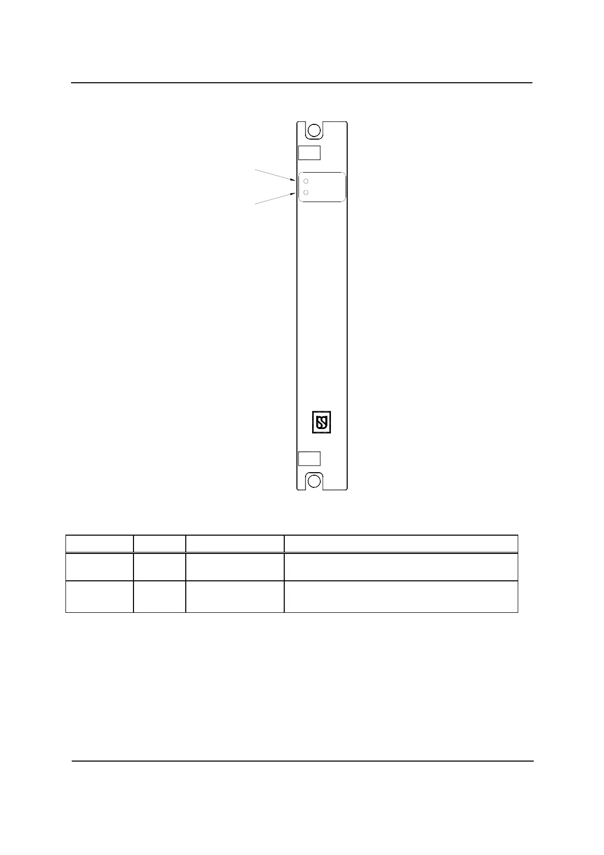
Figure - 3
Fig. 2-2 Ref Label Device Purpose
1
5V ON
LED (green)
When lit, indicates 5V-operating power on to other
Cardfile PCBs (If not lit refer to Figure-2.2.1).
2
VCOR
LED (green) When lit, indicates conditional power on to VCOR relay
(CPU diagnostics normal). (If not lit refer “CPS CLEAR
FUNCTION” details in Figure-3.4).
4.1.6. PHYSICAL I/O
The Physical I/O characteristics have been chosen to accommodate normal
railway and transit interface devices. Requirements for standard 24V DC
battery supply, Vital and Non-Vital relays, lamps and LED indications have
all been taken into account in determining voltage and current limits. The
voltage and current ranges specified for each I/O type are based on the
minimum and maximum requirements for these devices. The supply voltage
POWER SUPPLY
5V ON
VCOR
1
2
 Loading...