USSI Microlok II Functional description
UM-6800A Rev1.3 July 2005 Page 5 of 27
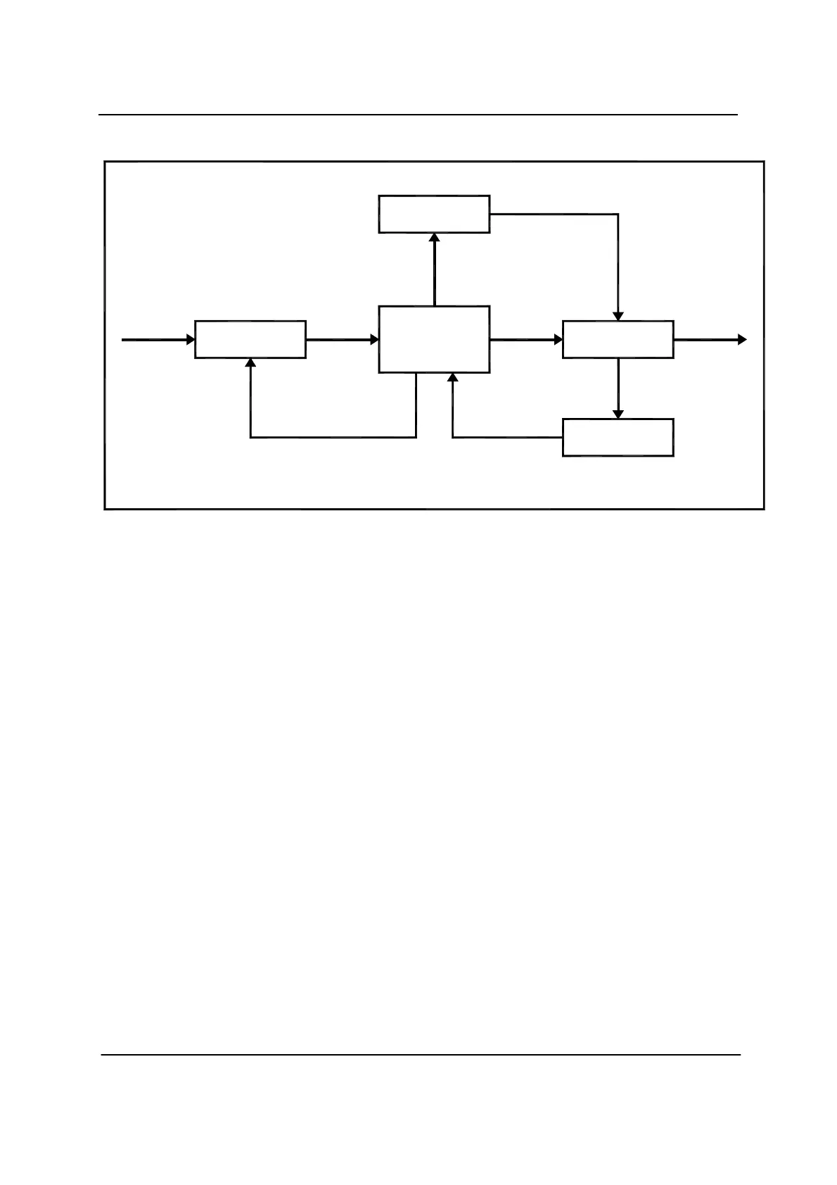
Figure-1
3.1. SYSTEM DESCRIPTION
The Microlok II interlocking system is a multi-purpose monitoring and
control system, which performs the following.
•
Drive Signal, Point, Crank Handle, LC Gate and Siding control relays
• Monitoring of Point position, track circuits occupancy and other field
inputs
• Vital CPU for overall system monitoring, control, diagnostics and data
recording
• Executive and application logic for vital interlocking functions
• Executive and application logic for non-vital control Panel & Operator
VDU functions
• Serial I/O channels for communicating with MLK II to MLK II, MLK II to
CAB/ Other Non-Vital application, Maintenance and Diagnostic function
4.1. MICROLOK II HARDWARE
The Microlok II system consists of modular card file-mounted equipment and
external peripheral devices that are used to interface the card file circuitry to
the field gears and other associated control systems. The following sections
provide an overview of the hardware.
Block Diagram of MICROLOK II System
Vital Conditional
Power Circuit
Microprocessor-
based Computer
System with vital
Software
Vital
Clock
Signal
Vital Input
Monitor
Vital
Inputs
Control
Signal
Output
Device
Control
Vital
Outputs
Vital Output
Monitor
Vital Output Power
Monitor
 Loading...