USSI Microlok II Functional description
UM-6800A Rev1.3 July 2005 Page 15 of 27
• Since the vital inputs are dealing with the detection of outdoor gears they
normally configured with double cutting arrangement.
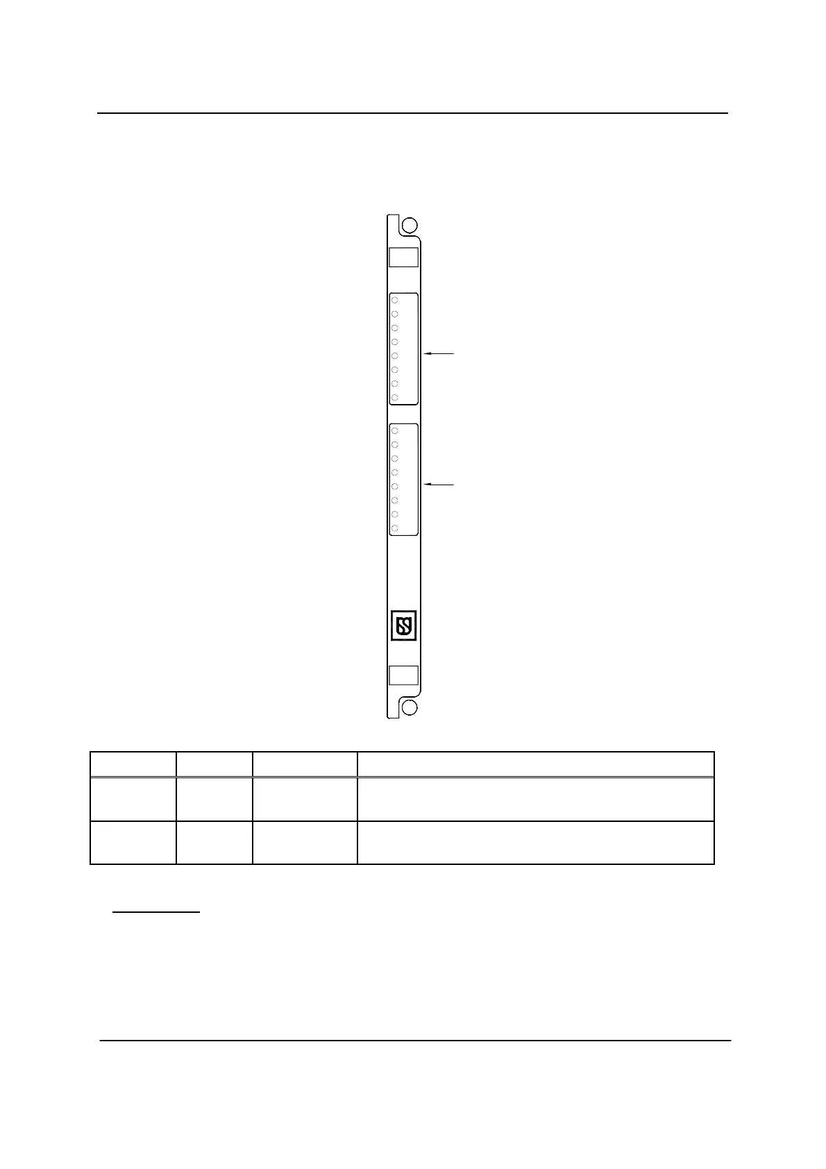
Figure – 6
Fig. 6 Ref Label Device Purpose
1
IN1 -IN8
green LEDs Monitor state of vital inputs 1 through 8. When lit, indicates
respective input is turned on.
2
IN9 -IN16
green LEDs Monitor state of vital inputs 9 through 16. When lit, indicates
respective input is turned on.
Vital Inputs
Vital inputs, which are in most cases, derived from the battery supply must
have the same range of inputs as the supply battery. To ensure reliable
operation, the Minimum ON thresholds (the levels above which an input
must read ON) were chosen to match the low ends of the battery ranges. The
IN16
1
IN 1
IN 2
IN 3
IN 4
IN 5
IN 6
IN 7
IN 8
IN 11
IN 15
IN 16
IN 13
IN 14
IN 12
IN 9
IN 10
2
 Loading...