Installation
LED indication (pos.1 и 4, g.1) is providing information for the device condition/status as follows:
- Duty Mode – ashes with discontinuous red and yellow light, every 16 seconds;
- Activated output – ashes with continuous red light;
- Activated input– ashes instantly with red light every 2 seconds;
- Fault condition (short-circuit or interruption in an input or an output ) – ashes with
continuous yellow light;
- Fault condition (activated isolator) - yellow LED ashing briey in 1 second;
- Fault condition (no power to the monitored output (when the supply voltage monitoring is
setted) yellow LED glow constantly;
- Service mode ( successfully created new conguration )- The red LED lights continuously;
- Service mode ( unsuccessfully created new congurationre ) - only yellow LED light;
2. Меchanical installation
2.1 Unpack the 7203 IO module /g. 3, step 1/
2.2 Remove the decorative plastic cover in front of the necessary terminals /g. 3, step 2/
2.3 7203 IO module need to be mounted on the wall using screw /g. 3, step 3A/ or on
DIN rail with 35mm width /g. 3, step 3В/
2.4 The 7203 IO module need to be installed in accordance to one of the connection diagram
described in point 3.2 .
2.5 After Fire panel ON and in case of new module wiring conguration, the module will enter in Fault
condition (exclude the rst module start-up when is connected in according to step 3A - then the module
will enter in Duty mode).
In order to "learn" the new conguration it is required to press and hold for 5 second the tactile button /g
3, step 5/. In case that operation is successfully done the module red LED indication will be activated
(in the left site of the module PCB) /g. 3 step 5/ the module enter in service/system mode. The module will
not communicate with Fie panel.
2.6 Restart the IFS 7002 panel /g. 3, step 6/
*After second or subsequent restart of re panel, the FD 7203 IO module (1 input/ 1 output) will retain the
last congured parameters (operation mode).
1. Conguring of the module operation mode
On the FD 7203 IO module PCB has built-in tactile button (position 2 g. 1). After pressing and holding it
for 5 second (refer point 2.5) the module will congure/recongure the operational mode in accordance to
the electrical installation diagram (point 3).
Note : In order to congure or recongure the FD 7203 IO module need to be powered from the signal loop.
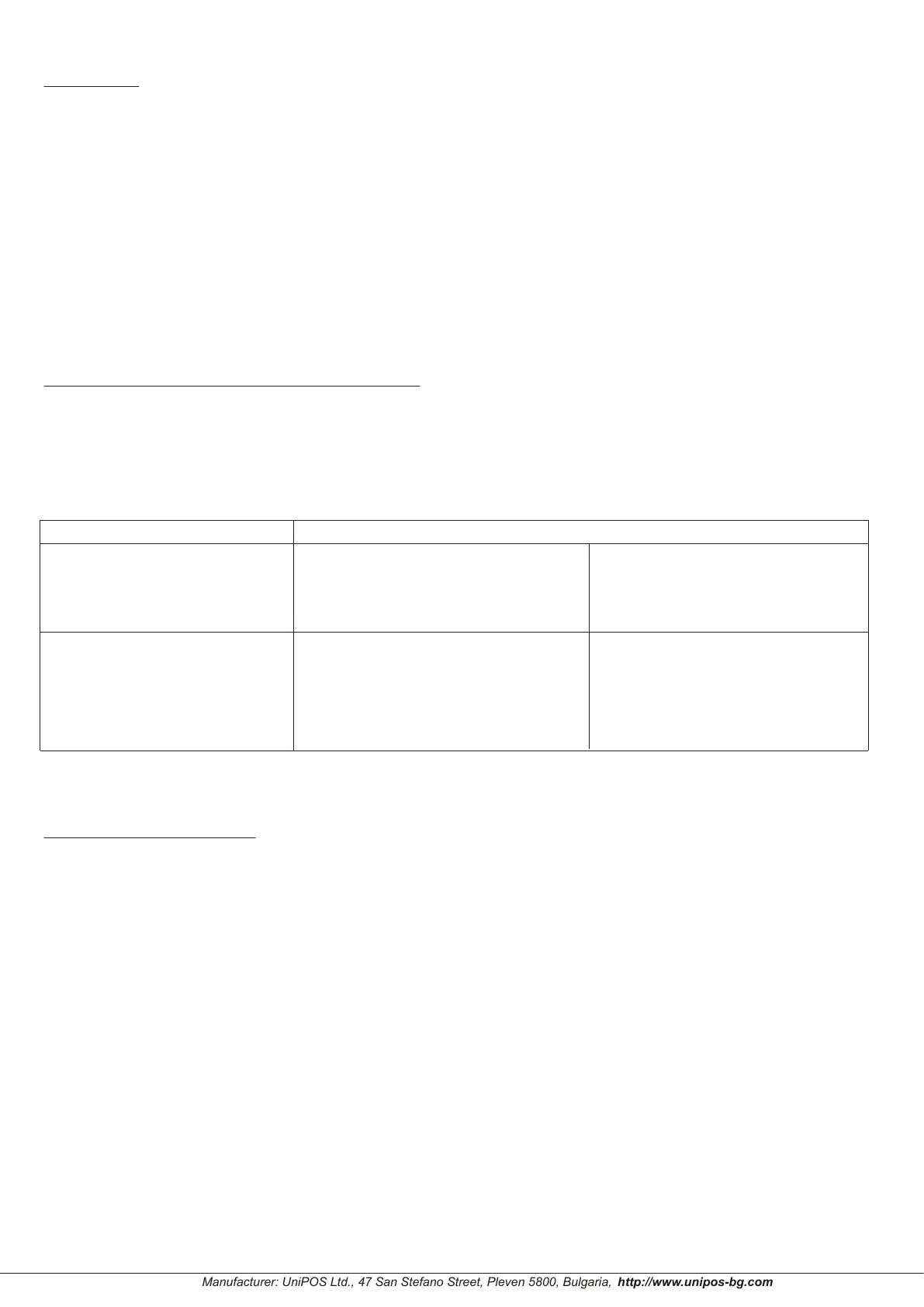
Fig
. 2 - Configuration using tactile button
Operating as monitored output
(Checking for power supply)
(Does not check for
power supply)
configuration type
input type
output type
Output is operating as a relay
with potential-free-functions
“C”, “NO” and “NC”
Check for short circuit
of the input
(it will be activated with additional
10КΩ connected in series )
Does not check for short
circuit of the input
(With connected EOL
element 10КΩ )
Manufacturer: UniPOS Ltd., 47 San Stefano Street, Pleven 5800, Bulgaria,
09/09.19
 Loading...