EasyManua.ls Logo

UNIRAC SolarMount - User Manual

UNIRAC SolarMount
6 pages
Print Icon
To Next Page IconTo Next Page
Loading...
© 2005 by UniRac, Inc.
All rights reserved.
Pub 050304-1ii
March 2005
UniRac welcomes input concerning the accuracy and user friendliness of
this publication. Please write to publications@unirac.com.
U.S. Des. Patent No. D496,248S. Other patents pending.
This manual details the
procedure for fl ush mounting
SolarMount to a pitched roof.
If your installation includes tilt
legs, see also the instructions
shipped with the leg kit.
Contents
Installer reponsibility . . . . . . 2
Laying out the
installation area . . . . . . . . . . . 2
Laying out L-feet . . . . . . . . . . 3
Installing L-feet . . . . . . . . . . . 3
Laying out standoffs . . . . . . . 4
Installing standoffs . . . . . . . . 4
Installing SolarMount
rails . . . . . . . . . . . . . . . . . . . . . 5
Installing the modules . . . . . 6
Wrenches and torque
Wrench Recommended
size torque (ft-lbs)
¼˝ hardware
7
16˝ 15
3
8˝ hardware
9
16˝ 30
Figure 3. Exploded view of a low-profi le installation
mounted fl ush to the roof with L-feet.
Mid
clamp
End
clamp
T-bolt slot
for module
mounting
Footing
bolt slot
L-foot
Part quantities
SolarMount
®
Rail Sets
No. of
3
8˝ footing
3
8˝ fl ange
Rail length (inches) rails L-feet bolts nuts
48 106 2 4 4 4
120 180 2 6 6 6
192 216 2 8 8 8
226 288 (w/ splice) 2 10 10 10
300 336 (w/ splice) 2 12 12 12
348 408 (w/ splice) 2 14 14 14
420 432 (w/ splice) 2 16 16 16
Top Mounting Clamp Sets, Sizes A F, G*, H†, and J
Modules End Mid ¼˝ module ¼˝x
5
8˝ ¼˝ ange
per row clamps clamps T-bolts safety bolts nuts
2 4 2 6 2 8
3 4 4 8 2 10
4 4 6 10 2 12
5 4 8 12 2 14
6 4 10 14 2 16
7 4 12 16 2 18
8 4 14 18 2 20
9 4 16 20 2 22
10 4 18 22 2 24
11 4 20 24 2 26
12 4 22 26 2 28
* In size G, end clamps and mid clamps are identical, except that end clamps
include spacers. For illustration, see page 14.
In size H, end clamps and mid clamps are identical. Hexhead bolts replace
T-bolts. For illustration, see page 14.
Stainless steel hardware can seize up, a
process called galling. To sig nifi cant ly re-
duce its like li hood, (1) apply lubricant to
bolts, preferably an anti-seize lu bri cant, available
at auto parts stores, (2) shade hardware prior to
installation, and (3) avoid spinning on nuts at high
speed. See Installation Supplement 910, Galling
and Its Prevention, at www.unirac.com.
Installation with Top Mounting Clamps
Installation Manual 201.1
Question and Answer IconNeed help?

Do you have a question about the UNIRAC SolarMount and is the answer not in the manual?

Summary

Installation with Top Mounting Clamps

Wrenches and torque

Details required wrenches and torque specifications for securing components during installation.

Installer responsibility

Outlines the installer's obligations regarding codes, product suitability, structural integrity, and safety.

Laying out the installation area

Guidance on positioning and measuring the roof area for module installation, considering rafter alignment.

Laying out L-feet

Instructions for marking L-foot lag bolt hole locations on rafters for flush mounting.

Installing L-feet

Steps for drilling, sealing, and securely fastening L-feet to roof rafters using lag bolts.

Laying out standoffs

Procedure for marking standoff lag bolt hole locations on underlayment over rafters for flashed installations.

Installing standoffs

Instructions for drilling, sealing, and fastening standoffs to rafters, including flashing.

Installing SolarMount rails

Guidance on preparing, aligning, and securely mounting SolarMount rails to footings or standoffs.

Installing the modules

Steps for prewiring, connecting, and securing PV modules to the installed rails using clamps and bolts.

Overview

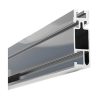
The UniRac SolarMount is a mounting structure designed for photovoltaic (PV) arrays, specifically for flush mounting on pitched roofs. It is engineered to provide a secure and stable platform for solar modules, ensuring compliance with building codes and optimal performance. The system is designed for ease of installation and offers various configurations to suit different roof types and module requirements.

Function Description:

The primary function of the SolarMount system is to securely attach solar modules to a pitched roof, creating a PV array. It achieves this by providing a framework of rails that support the modules, which are then fastened to the roof structure using L-feet or standoffs. The system is designed to withstand environmental loads such as wind and snow, ensuring the long-term stability and safety of the PV installation. It also facilitates proper airflow under the modules, which can help in cooling and enhancing their performance, especially in hotter climates. The system accommodates different module types and sizes through various clamping mechanisms.

Usage Features:

The SolarMount system offers several usage features that enhance its versatility and ease of installation:

  • Mounting Options: The system supports two primary methods for attaching to the roof:
    • L-feet: Used for installations through existing roofing materials like asphalt shingles or sheet metal. L-feet are fastened directly to the roof rafters.
    • Standoffs: Employed for flashed installations, typically with tile and shake shingles. Standoffs are designed to integrate with collared or aluminum flashings to maintain the waterproof integrity of the roof.
  • Profile Modes: The installation can be configured in two profile modes:
    • Low-profile mode: Rails are laid out perpendicular to the rafters, offering a more aesthetically pleasing installation with a lower overall height.
    • High-profile mode: Rails are laid out parallel to the rafters, which maximizes airflow under the modules, potentially enhancing performance by keeping them cooler.
  • Rail Splicing: For longer arrays, SolarMount splice bars can be used to connect rail sections. This feature allows for flexible array sizing and simplifies logistics by enabling the use of shorter rail segments. However, installers are advised to consult UniRac regarding thermal expansion issues when using multiple splices per rail.
  • Module Clamping: The system utilizes various clamps to secure modules to the rails:
    • End Clamps: Used at the ends of each row of modules to secure the outermost modules.
    • Mid Clamps: Placed between adjacent modules to secure their shared edges.
    • T-bolts and Flange Nuts: These are the primary fasteners used to attach clamps to the rails and rails to the footings. The design allows for easy sliding within the rail slots for precise positioning.
  • Adjustability: The L-feet and standoffs offer some adjustability to accommodate variations in roof structure and to ensure the rails are level and properly aligned. The slotted design of the L-feet allows for fine-tuning of their position.
  • Prewiring Facilitation: For modules with standard J-boxes, the system encourages prewiring modules with intermodule cables before installation on the roof, enhancing safety and efficiency.
  • Module Alignment: The installation process includes guidelines for aligning rail ends and modules to ensure a neat and structurally sound array. For high-profile installations, specific alignment of the rail ends to the lower edge of the roof is recommended for safety.
  • Hardware Compatibility: The system uses stainless steel hardware, which is durable but requires proper handling to prevent galling (seizing). Lubrication and careful installation are recommended.

Maintenance Features:

While the SolarMount system itself requires minimal maintenance, certain aspects contribute to its long-term durability and performance:

  • Durable Materials: The components are made from robust materials designed to withstand outdoor conditions, including aluminum for rails and stainless steel for hardware, ensuring longevity.
  • Corrosion Resistance: The use of stainless steel hardware and anodized aluminum rails provides excellent resistance to corrosion, which is crucial for outdoor installations.
  • Waterproof Integrity: The design emphasizes maintaining the waterproof integrity of the roof. Standoffs are specifically designed to work with flashings, and L-feet installations require appropriate sealants to prevent water ingress.
  • Regular Checks: Although not explicitly detailed as a maintenance feature of the mounting system itself, the manual implies the importance of checking all flange nuts on T-bolts for secure fastening after installation. This ensures the continued stability of the array over time.
  • Clearance for Airflow: The high-profile mounting option is designed to maximize airflow under the modules, which helps in cooling them. Maintaining this clearance is a passive maintenance feature that contributes to the modules' efficiency and lifespan.
  • Warranty: UniRac provides a 10-year limited Product Warranty and a 5-year limited Finish Warranty, covering defects in material and workmanship, and visible peeling, cracking, or chalking of the anodized finish under normal atmospheric conditions. This warranty underscores the expected durability and quality of the product, reducing the need for frequent repairs or replacements due to manufacturing issues. However, the warranty is void if installation instructions are not followed or if the product is modified without authorization. It also excludes installations in corrosive atmospheric conditions.

In summary, the UniRac SolarMount system is a comprehensive and adaptable solution for mounting solar PV modules on pitched roofs, designed with an emphasis on structural integrity, ease of installation, and long-term reliability.

UNIRAC SolarMount Specifications

General IconGeneral
MaterialAluminum
Corrosion ResistanceYes
Installation TypeRoof-mounted
BrandUNIRAC
ModelSolarMount
CompatibilitySolar panels
Weight CapacityVaries by model