IMP120-17
www.ueonline.com
120 Series
Explosion-Proof Pressure and
Differential Pressure Switches
Types
J120, J120K, H121, H121K, H122, H122K
UNITED ELECTRIC
CONTROLS
Installation and Maintenance
Instructions
IMP120-17
*Proof Pressure: The maximum pressure to which a pressure sensor
may be occasionally subjected, which causes no permanent damage
(e.g., start-up testing). The unit may require re-gapping. (See Part
II- Adjustments)
**Over Range Pressure: The maximum pressure to which a pressure
sensor may be continuously subjected without causing damage and
maintaining set point repeatability.
***Working Pressure Range The pressure range within which two
opposing sensors can be safely operated and still maintain set point
repeatability.
THIS DEVICE DOES NOT HAVE ANY FIELD REPLACEABLE
PARTS. ANY SUBSTITUTION OF COMPONENTS MAY IMPAIR
SUITABILITY FOR CLASS I, DIVISION 1.
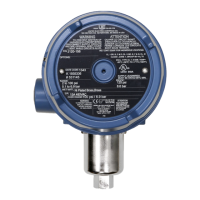
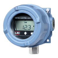
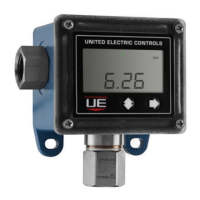
The 120 Series pressure and differential pressure switches are
actuated when a bellows, diaphragm or piston sensor responds to
a pressure change. This response at a pre-determined set point(s)
actuates a SPDT, DPDT or dual SPDT snap-acting microswitch(es),
which convert the pressure signal into an electrical signal. Control
set point(s) may be varied by turning the internal adjustment hex
(J120 & J120K models) or the external knob and pointer(s) (H121,
H121K, H122, & H122K models, see picture above) according to the
procedures outlined. (See Part II - Adjustments)
Please refer to product bulletin for product specifications. Product
bulletins may be found at www.ueonline.com.
UE declarations and third party issued certifications are available for
download at www.ueonline.com/prod_approval.
Date code format on nameplate is “YYWW” for year and week.
Part I -Installation
Tools Needed–Screwdriver/Adjustable Wrench to 1-1/2”
MOUNTING
TO PREVENT ELECTROSTATIC DISCHARGE, WIPE DOWN COVER
AND ENCLOSURE OF ANY DUST BUILD UP BEFORE REMOVING
COVER.
INSTALL DEVICE WHERE SHOCK, VIBRATION AND
TEMPERATURE FLUCTUATIONS ARE MINIMAL. DO NOT MOUNT
DEVICE IN AMBIENT TEMPERATURES THAT EXCEED THE
LIMITS ON THE NAMEPLATE FOR THE APPROPRIATE AREA
GENERAL
MISUSE OF THIS DEVICE MAY CAUSE EXPLOSION AND
PERSONAL INJURY. THESE INSTRUCTIONS MUST BE
THOROUGHLY READ AND UNDERSTOOD BEFORE DEVICE IS
INSTALLED.
THIS DEVICE IS SUITABLE FOR USE IN CLASS I, DIVISION 1,
GROUPS B, C AND D; CLASS II, DIVISION 1, GROUPS E, F AND
G; CLASS III
; OR NON-HAZARDOUS LOCATIONS ONLY.
ENCLOSURE TYPE 4X, 7 & 9.
The device has been certified in accordance with the
applicable requirements of the following standards:
• IEC 60079-0, 6
th
Edition, Revision Date 2013/12
• IEC 60079-1, 7
th
Edition, Revision Date 2014/06
• IEC 60079-1, 6
th
Edition, Issue Date 2007/04
• IEC 60079-31, 2
nd
Edition, Issue Date 2013/11
• EN 60079-0:2012+A11:2013
• EN 60079-1:2007
• EN 60079-31:2014
THIS DEVICE IS ATEX CERTIFIED FOR EQUIPMENT CATEGORY
2. SUITABLE FOR APPROPRIATE USE IN GAS ZONE 1 & DUST
ZONE 21 APPLICATIONS.
DEMKO 09 ATEX 0815573X
0539 IECEx UL 03.0001X
II 2 G Ex db IIC T6 Gb
II 2 D Ex tb IIIC T85°C Db IP66
-40°C≤Tamb.≤+75°C
BEFORE INSTALLING, CHECK THE SENSOR MODEL SELECTED
FOR COMPATIBILITY TO THE PROCESS MEDIA IN CONTACT
WITH THE SENSOR AND WETTED PARTS.
TO PREVENT IGNITION OF HAZARDOUS ATMOSPHERES,
DISCONNECT SUPPLY CIRCUITS BEFORE OPENING. KEEP
COVER TIGHT WHILE CIRCUITS ARE ENERGIZED.
PROOF PRESSURE* LIMITS STATED IN THE LITERATURE
AND ON NAMEPLATE MUST NEVER BE EXCEEDED, EVEN BY
SURGES IN THE SYSTEM. OCCASIONAL OPERATION OF DEVICE
UP TO MAXIMUM PRESSURE IS ACCEPTABLE (E.G., START-UP, TESTING).
CONTINUOUS OPERATION SHOULD NOT EXCEED THE DESIGNATED
OVER RANGE PRESSURE** OR WORKING PRESSURE RANGE***.
Please read all instructional literature carefully and thoroughly before starting. Refer to the final page for the listing of Recommended
Practices, Liabilities and Warranties.